Hardware machining method

A processing method and hardware technology, applied in metal processing equipment, manufacturing tools, grinding machines, etc., can solve the problems of low grinding and polishing efficiency, inability to grind parts on both sides, etc., and achieve the effect of speeding up grinding efficiency, uniform grinding, and improving grinding efficiency

Inactive Publication Date: 2018-05-18
华汉致信(宁波)供应链管理有限公司
View PDF5 Cites 3 Cited by
  • Summary
  • Abstract
  • Description
  • Claims
  • Application Information

AI Technical Summary

Problems solved by technology

[0004] The following technical problems exist in the prior art: the parts cannot be ground on both sides, and the efficiency of grinding and polishing is low

Method used


Image

  • Hardware machining method
  • Hardware machining method
  • Hardware machining method

Examples


Embodiment Construction

[0028] The present invention will be described in further detail below by means of specific embodiments:

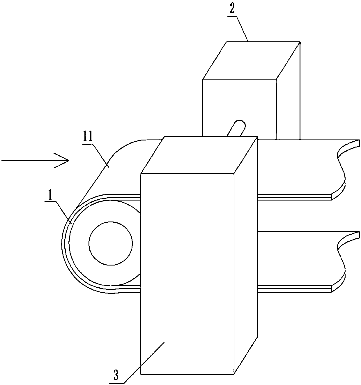
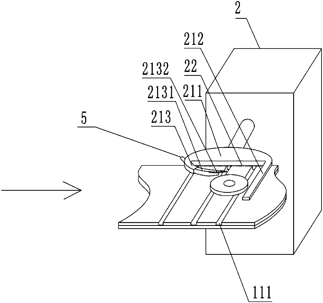
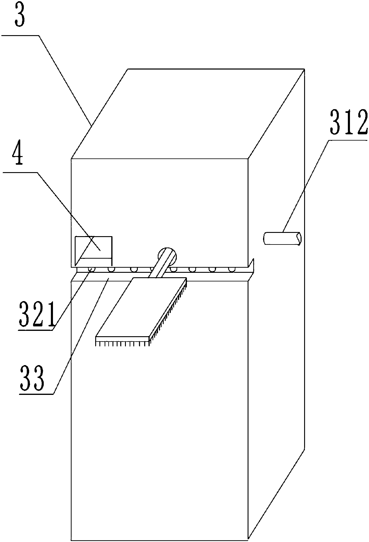
[0029] The reference signs in the accompanying drawings of the specification include: the conveying surface 1, the grinding layer 11, the dust collecting tank 111, the grinding part 2, the cleaning brush 22, the plate body 211, the stop rod 212, the arc-shaped outer cover 213, and the arc-shaped limit block 2131 , Baffle plate 2132, Dust suction part 3, Dust suction tube 31, Dust suction pipe 311, Dust discharge pipe 312, Bar box 32, Dust suction hole 321, Chute 33, Placement cavity 34, Strip chute 341, Fixed Plate 342, insertion port 4, threaded rod 5, push rod 6, extension rod 61, slide rod 62, polishing brush 63, push block 64, L-shaped rod 7, connecting rod 71.

[0030] In order to achieve the above object, the basic scheme of the present invention is as follows:

[0031] like figure 1 and figure 2 As shown, a metal processing method, the steps are as follows:

...


PUM


Abstract

The invention relates to the technical field of polishing and grinding, in particular to a hardware machining method. The hardware machining method includes the steps of step 1, preparing of a grinding device; step 2, grinding for the lower surface; step 3, grinding for the upper surface; and step 4, once more transmitting. According to the hardware machining method, metal parts can be grinded onthe two surfaces, and the efficiency of the polishing and the grinding can be improved.

Description

technical field [0001] The invention relates to the technical field of polishing and grinding, in particular to a metal processing method. Background technique [0002] At present, in the polishing and grinding process of existing metal parts, most of them still adopt the traditional manual fixed polishing and grinding method. First, the parts are placed on the grinding table, and then they are fixed by manpower, and then polished with sandpaper. Then remove the burrs on the surface of the metal parts; more grinding debris will appear during the grinding process, which will pollute the environment. [0003] The patent with the notification number CN201109069Y discloses a dust-absorbing and polishing table, which includes a workbench and a box body. One end of the box body is provided with an exhaust fan; the other end is provided with a distribution box, a reduction motor and a pulley; The structure of the drum is a cylindrical frame, and its outer peripheral surface is wra...

Claims


Application Information

Patent Timeline
Patent Type & Authority Applications(China)
IPC IPC(8): B24B19/00B24B55/06B24B55/12
CPCB24B19/00B24B55/06B24B55/12
Inventor 邱红光
Owner 华汉致信(宁波)供应链管理有限公司
Why Eureka
Try Eureka