Lower disc transmission mechanism of grinder or polisher

A technology of transmission mechanism and polishing machine, which is applied in the directions of grinding machine parts, grinding/polishing equipment, grinding feed motion, etc. Long and other problems, to achieve the effect of good processing quality

Pending Publication Date: 2018-07-24
SHENZHEN SAPPHIRE AUTOMATION EQUIP
View PDF1 Cites 4 Cited by
  • Summary
  • Abstract
  • Description
  • Claims
  • Application Information

AI Technical Summary

Problems solved by technology

Secondary installation and processing will cause damage to the workpiece or non-parallel processing, which will make the workpiece scrapped
However, the working disk of this invention is driven by the motor to rotate through the first transmission assembly to realize multi-station polishing, because the first transmission assembly includes a belt drive and a reduction mechanism, the transmission chain is very long, and the gap accumulated in the transmission chain is too large to make it work. When the disc is stopped, it cannot be precisely positioned and locked, and the working disc shakes left and right on the station, which affects the polishing quality of the workpiece
[0004] In addition, because the position of the detachable main shaft cannot be accurately positioned, the manipulator cannot be positioned to pick and place the workpiece, which increases the auxiliary time for product pick-and-place and reduces production efficiency.

Method used


Image

  • Lower disc transmission mechanism of grinder or polisher
  • Lower disc transmission mechanism of grinder or polisher
  • Lower disc transmission mechanism of grinder or polisher

Examples


Embodiment Construction

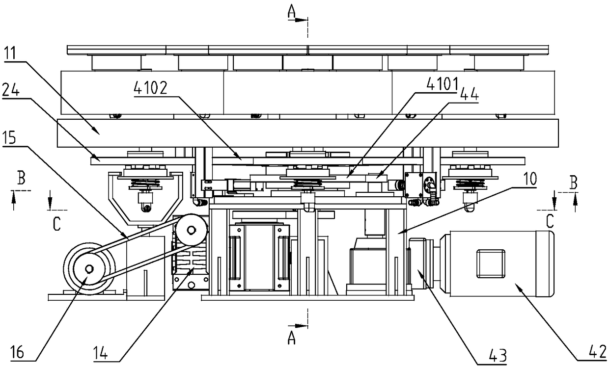
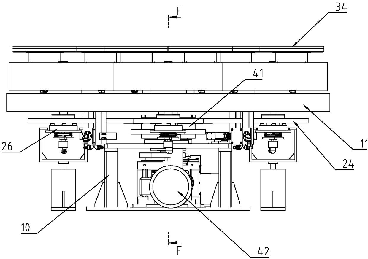
[0037] The lower plate transmission mechanism of the polishing machine in embodiment 1 of the present invention is as follows: Figure 1 to Figure 10 Shown, comprise frame 10, 4 lower disk assemblies, lower disk revolution mechanism and lower disk rotation mechanism.

[0038] The lower plate revolution mechanism includes a main tray 11, a main shaft 12, a bearing seat 13, a final reducer 14, a belt drive 15, a main motor 16, a main shaft gear 17, a divider 18, a divider gear 19 and 4 clutch mechanism driving devices.

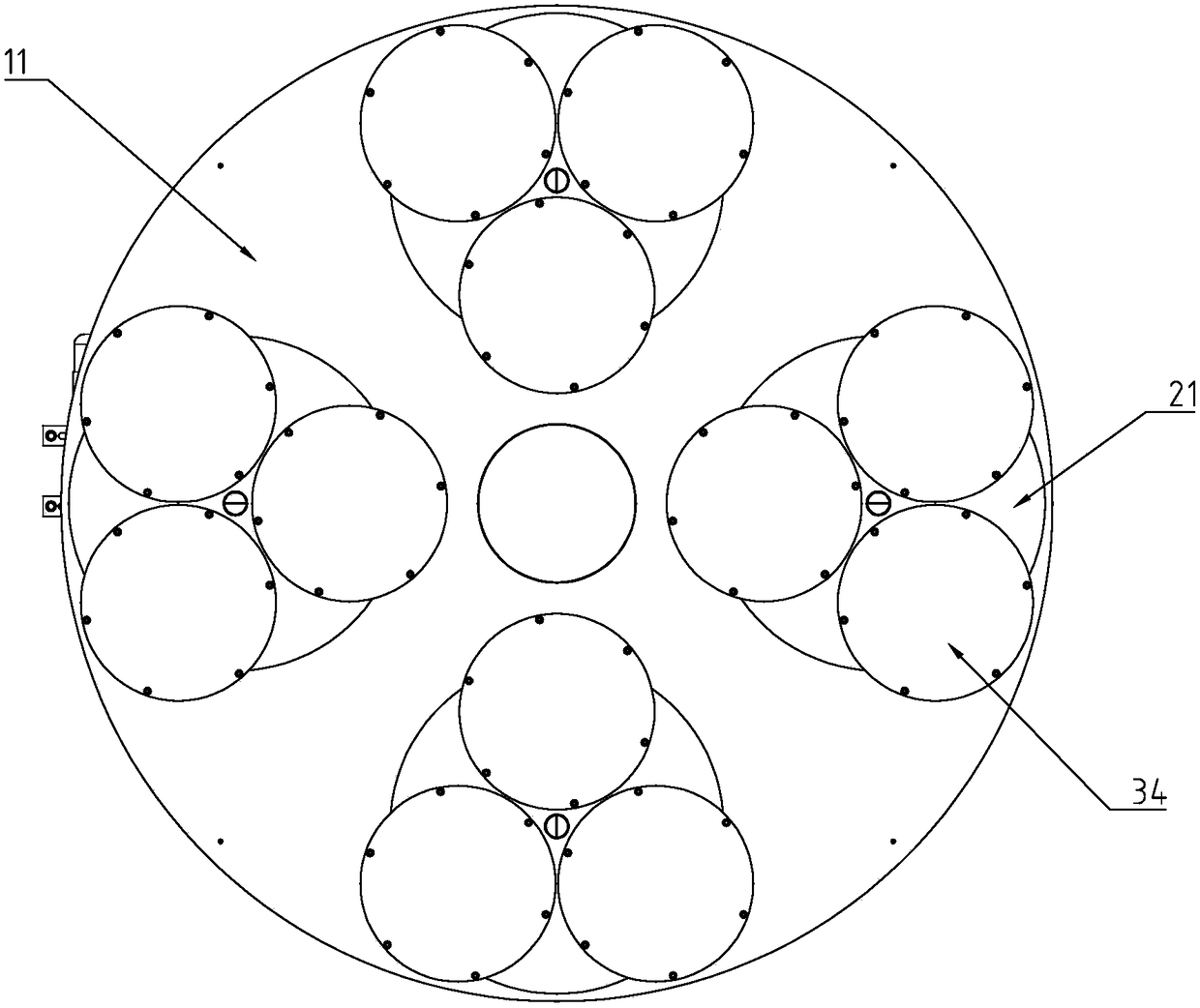
[0039] Bearing block 13 is fixed on frame 10 middle parts. The main shaft 12 is vertically installed in the bearing housing 13 and supported by the bearing 1301 . The main tray 11 is fixed on the upper end of the main shaft 12, and the main tray 11 has four supporting holes 1101 for installing the lower plate assembly.

[0040] The cam divider 18 is a four-position cam divider. The cam divider 18 is driven by the main motor 16 through the belt drive 15 and th...


PUM


Abstract

The invention discloses a lower disc transmission mechanism of a grinder or a polisher. The lower disc transmission mechanism comprises a rack, a plurality of lower disc assemblies, a lower disc revolution mechanism and a lower disc autorotation mechanism. The lower disc revolution mechanism comprises a main tray, a spindle, a bearing seat, a main motor and a cam divider. The bearing seat is fixedto the rack; the spindle is vertically mounted in the bearing seat and driven by the main motor; the main tray is fixed to the upper end of the spindle; and the cam divider is driven by the main motor, the spindle is driven by the cam divider, and the position number of the cam divider is the same as the number of the lower disc assemblies. The spindle of the main tray is driven by the cam divider, the cam divider is a high-precision revolution device, thus a transmission gap does not exist, and the self-locking effect can be achieved; and the main tray driven by the cam divider can be precisely positioned when stopped, and a working disc does not shake circumferentially after being stopped, so that the workpiece machining quality is good.

Description

technical field] [0001] The invention relates to a grinding machine or a polishing machine, in particular to a lower plate transmission mechanism of a grinding machine or a polishing machine. Background technique] [0002] The single-side polishing machine is suitable for processing thin precision parts of ultra-thin hard and brittle materials. The traditional lower plate drive mechanism is processed by the revolution and rotation of multiple grinding discs. When the workpiece on one of the grinding discs is not completely processed after processing When the requirements are met, it is necessary to accumulate the majority after disassembly, and then install and process the second time. Secondary installation and processing will cause damage to the workpiece or non-parallel processing, which will make the workpiece scrapped. [0003] The invention with application number CN201710672447.7 discloses an intelligent multi-segment curved surface polishing machine, including: a wo...

Claims


Application Information

Patent Timeline
Patent Type & Authority Applications(China)
IPC IPC(8): B24B47/12B24B41/00B24B27/00
CPCB24B27/0023B24B27/0069B24B27/0076B24B41/005B24B47/12
Inventor 吴秀凤李创宇张彦志张得意
Owner SHENZHEN SAPPHIRE AUTOMATION EQUIP
Why Eureka
Try Eureka