Heat exchange device

A technology for heat exchange devices and heat exchangers, applied in heat transfer modification, heat exchange equipment, heat exchanger fixation, etc., can solve the problems of increasing the flow resistance of heat exchange fluid, increasing the cleaning frequency of heat exchangers, and heat exchange capacity Improvement and other issues to achieve the effect of reducing heat transfer area, reducing heat transfer, and increasing heat dissipation

Inactive Publication Date: 2018-07-31
UNIV OF SHANGHAI FOR SCI & TECH
View PDF6 Cites 10 Cited by
  • Summary
  • Abstract
  • Description
  • Claims
  • Application Information

AI Technical Summary

Problems solved by technology

[0003] The existing heat exchange design for energy storage is that the heat exchange tube is in direct contact with the energy storage medium, but limited by volume and space, the contact area between the heat exchange tube and the energy storage medium is the actual area of ​​the outer surface of the heat exchange tube, and the energy storage medium stores The heat is transferred to the heat exchange tube mainly by the thermal conductivity of the material itself, so the heat exchange efficiency is very low
[0004] In addition, at this stage, the main methods for improving the material structure of the heat exchanger to enhance heat include: inner micro-rib tubes, adding choke rings, etc. Although this processing method by adding inner micro-rib tubes and choke rings The technology is relatively mature, but its heat transfer capacity is difficult to improve, and due to the use of structures such as micro-ribbed tubes to enhance heat transfer, its flow resistance has always been maintained at a high value, increasing the flow resistance of the heat transfer fluid, and at the same time Increased cleaning frequency of heat exchangers

Method used


Image

  • Heat exchange device
  • Heat exchange device
  • Heat exchange device

Examples


Embodiment Construction

[0019] In order to make the technical means, creative features, goals and effects achieved by the present invention easy to understand, the following embodiments illustrate the heat exchange device of the present invention in detail with reference to the accompanying drawings.

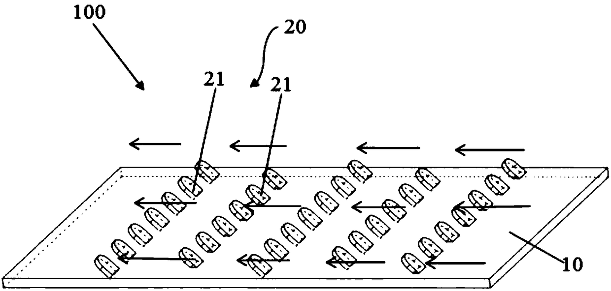
[0020] figure 1 It is a structural schematic diagram of the heat exchange device in the embodiment of the present invention.

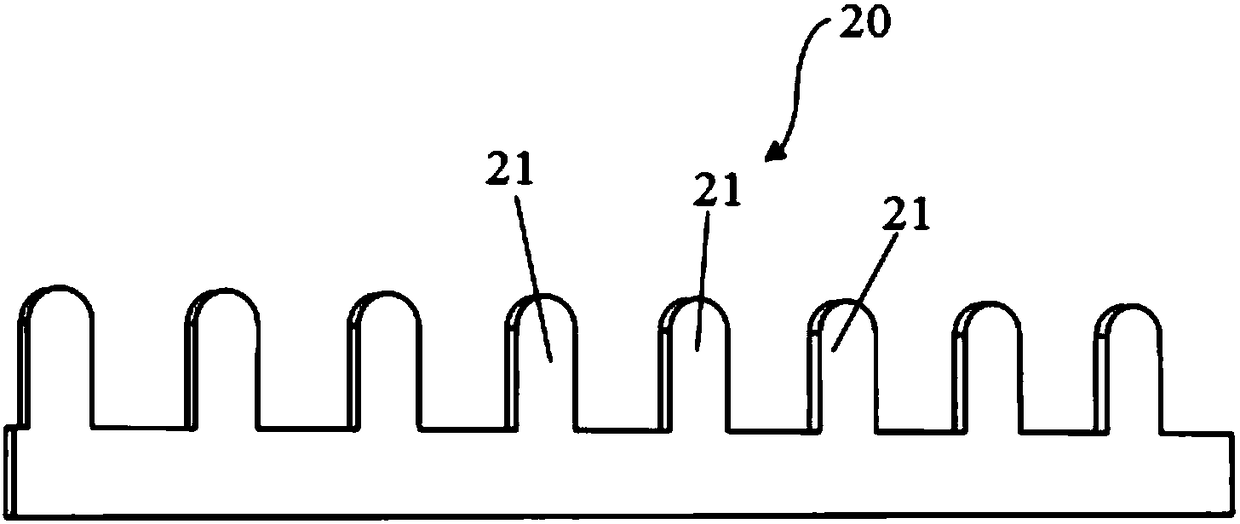
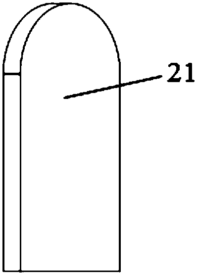
[0021] like figure 1 As shown, the heat exchange device 100 is a plate-type one-sided heat exchange device, which is made of metal materials, and the heat exchange efficiency of the heat exchange device is adjusted according to the temperature difference between the cold and hot fluids or the amount of heat exchange, including the heat exchanger body 10 And the heat exchange assembly 20. The heat exchanger body 10 and the heat exchange component 20 are integrally formed. Both the heat exchanger body 10 and the heat exchange component 20 are made of memory metal or a composite...


PUM


Abstract

The invention provides a heat exchange device. The heat exchange device comprises a heat exchanger body and heat exchange assemblies, hot fluid and cold fluid used for exchanging heat with the hot fluid are arranged on the two sides of the heat exchanger body in a communicating mode, the heat exchange assemblies are arranged on at least one side of the heat exchanger body and each are provided with a plurality of heat exchange component s arranged at predetermined intervals, the heat exchange efficiency is adjusted according to the temperature difference between the cold fluid and the hot fluid, and one end of each heat exchange component is fixed to the heat exchanger body, wherein, the heat exchange components are made of memory metal or composite materials containing the memory metal. The heat exchange device has the advantages that when the heat exchange amount is relatively large or the heat exchange temperature difference is relatively large, the other ends of the heat exchange components are erected at larger angles, so that the heat exchange area of the heat exchange device is increased, and then the heat exchange amount is increased; and when the heat exchange amount or the heat exchange temperature difference is decreased, the other ends of the heat exchange components are erected at smaller angle or are attached to the heat exchanger body, so that the heat exchange area of the heat exchange device is decreased, then the heat exchange amount is decreased, and therefore biomimetic heat dissipation can be realized, the heat exchange efficiency of the heat exchange device can be effectively improved.

Description

technical field [0001] The invention relates to the field of energy-saving heat exchange, in particular to a heat exchange device. Background technique [0002] In energy storage and heat exchange devices, the heat exchange efficiency is the focus of the index for evaluating its performance. Due to the limitation of thermal conductivity, many media with excellent energy storage performance have slow heat storage and heat release speeds, resulting in low performance of energy storage devices. Enhancing the heat exchange capacity of heat exchangers has always been an urgent need in industrial production for the normal and efficient work of heat dissipation and heat transfer equipment. At the same time, improving the heat transfer performance in engineering applications can greatly enhance the effect of energy saving and emission reduction. [0003] The existing heat exchange design for energy storage is that the heat exchange tube is in direct contact with the energy storage...

Claims


Application Information

Patent Timeline
Patent Type & Authority Applications(China)
IPC IPC(8): F28F3/04F28F1/40F28F13/00F28F13/06F28F21/08
CPCF28F3/04F28F1/40F28F13/00F28F13/06F28F21/081F28F2013/001F28F2275/06F28F2275/068
Inventor 胡峰王海民高涌东
Owner UNIV OF SHANGHAI FOR SCI & TECH
Why Eureka
Try Eureka