Laser-type reflector coordinate system calibration method and laser navigation system

A technology of laser reflection and laser navigation, which is applied in the field of robot navigation, can solve the problems of low precision of navigation technology, achieve the effects of improving positioning accuracy, improving accuracy and precision, and improving navigation accuracy

Pending Publication Date: 2018-08-17
浙江众导机器人科技有限公司
View PDF4 Cites 8 Cited by
  • Summary
  • Abstract
  • Description
  • Claims
  • Application Information

AI Technical Summary

Problems solved by technology

[0003] The purpose of the present invention is to solve the problem of low precisio

Method used


Image

  • Laser-type reflector coordinate system calibration method and laser navigation system
  • Laser-type reflector coordinate system calibration method and laser navigation system
  • Laser-type reflector coordinate system calibration method and laser navigation system

Examples


Embodiment Construction

[0019] In order to make the objectives, technical solutions and advantages of the present invention clearer, the technical solutions in the embodiments of the present invention will be clearly described below in conjunction with the accompanying drawings in the embodiments of the present invention. Obviously, the described embodiments are the embodiment of the present invention Some, but not all, embodiments. Based on the embodiments of the present invention, all other embodiments obtained by those skilled in the art without making creative efforts fall within the protection scope of the present invention.

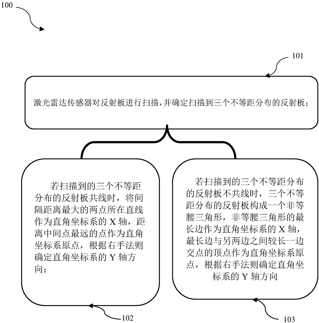
[0020] In order to solve the problem of low accuracy and precision of the existing coordinate system calibration. The invention provides a coordinate system calibration method of a laser reflector, such as figure 1 The flow chart shown, its steps include:

[0021] S101: The lidar sensor scans the reflector, and scans three reflective points that are not equidistantly dis...


PUM


Abstract

The present invention provides a laser-type reflector coordinate system calibration method. The method comprises the steps of: scanning a reflector by a laser radar sensor to scan three unequally spaced reflection points in order; if the scanned three unequally spaced reflection points are collinear, taking a straight line where the two points have the largest interval distance are located as an Xaxis of a rectangular coordinate system, taking a point the farthest to the middle point as an original point, and determining a Y-axis direction of the rectangular coordinate system according to a right-hand rule; and if the scanned three unequally spaced reflection points are not collinear, allowing the three unequally spaced reflection points to form a non-isosceles triangle, taking the longest side of the non-isosceles triangle as an X-axis of the rectangular coordinate system, taking a vertex of an intersection point of the longest side and the longer side in other two sides as an original point, and determining a Y-axis direction of the rectangular coordinate system according to a right-hand rule. The method can calibrate the unique rectangular coordinate system and employs the laser for scanning to increase the location precision and reduce the navigation errors of a robot.

Description

technical field [0001] The invention relates to the technical field of robot navigation, in particular to a method for calibrating a coordinate system of a laser reflector and a laser navigation system. Background technique [0002] With the rapid development of industrial technology and the continuous advancement of robot technology, the application of sports equipment is also constantly expanding. During the operation of most sports equipment, navigation, as the core technology of autonomous driving, is of great significance to the safe driving of sports equipment. The coordinate system calibration of existing robot navigation equipment is generally realized by mechanical constraint points. But using this method to calibrate the coordinate system is not high enough, and it is easy to make the robot deviate during the navigation process. Contents of the invention [0003] The purpose of the present invention is to solve the problem of low precision in the coordinate sys...

Claims


Application Information

Patent Timeline
IPC IPC(8): G01S17/06
CPCG01S17/06
Inventor 韩勇张腾飞
Owner 浙江众导机器人科技有限公司
Why Eureka
Try Eureka