A self-focusing method of optical scanning holography based on edge gray level difference function

An optical scanning and self-focusing technology, applied in the field of optical scanning holography and self-focusing, to achieve the effect of high-efficiency self-focusing problem, strong practicability and strong applicability

Inactive Publication Date: 2019-06-21
UNIV OF ELECTRONICS SCI & TECH OF CHINA
View PDF9 Cites 0 Cited by
  • Summary
  • Abstract
  • Description
  • Claims
  • Application Information

AI Technical Summary

Problems solved by technology
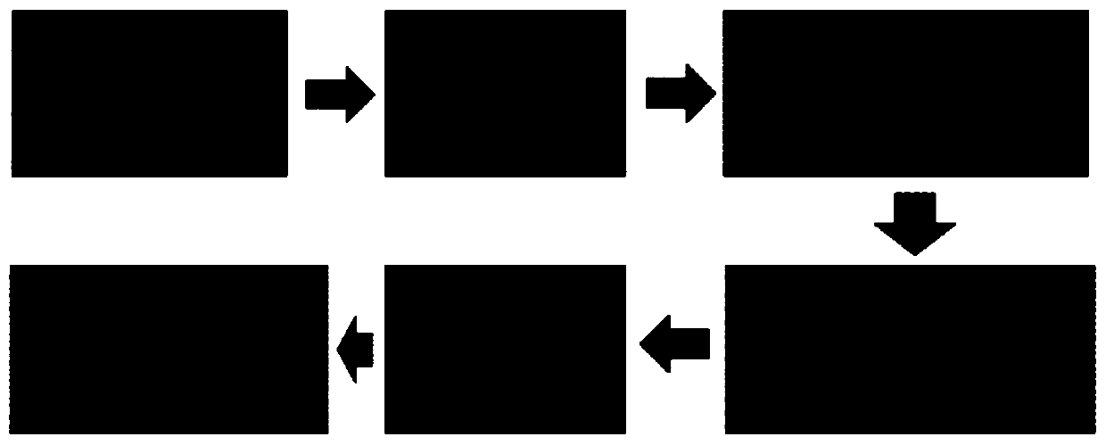
The present invention proposes an evaluation function of the focused image. There is a difference between the focused image and the defocused image on the edge. The present invention further amplifies this difference to form an evaluation function of the focused image, which solves the problem of the holographic image well. For the self-focusing problem, compared with the existing technology, the edge gray difference (EGD) function is simple to calculate and has high accuracy. It can realize the self-focusing problem of various types of holographic images, and has strong applicability.

Method used


Image

  • A self-focusing method of optical scanning holography based on edge gray level difference function
  • A self-focusing method of optical scanning holography based on edge gray level difference function
  • A self-focusing method of optical scanning holography based on edge gray level difference function

Examples


Embodiment 1

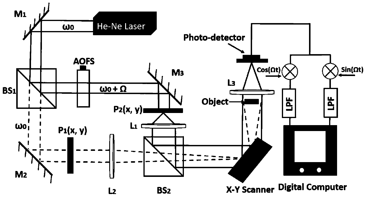
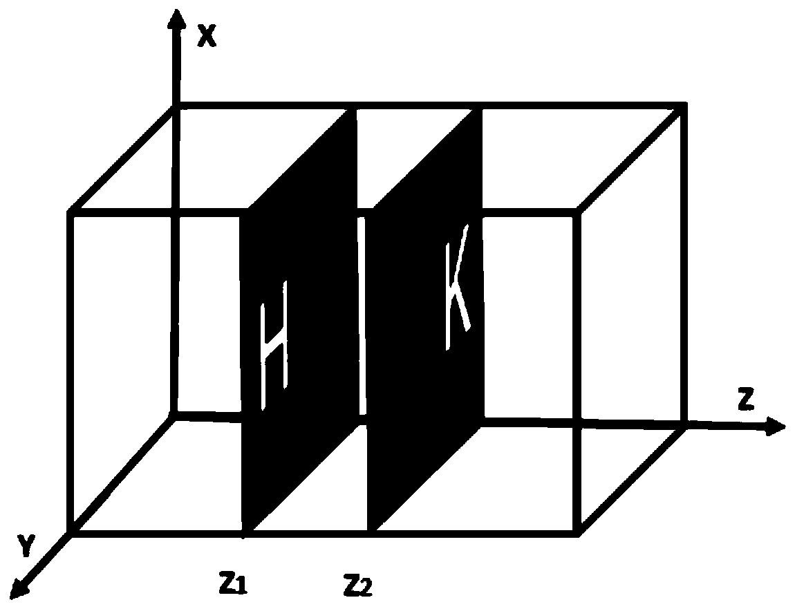
[0073] The basic structure of the experiment adopted in this embodiment is as follows: figure 2 Shown, wherein the wavelength λ=632.8nm of He-Ne laser Laser Laser, the focal length of convex lens L1 is 200mm, the focal length of L2 is 75mm, the object to be measured of embodiment is as image 3 As shown, the cross-section matrix size of the sliced ​​object is 300×300. The reconstruction range of the embodiment is [9.5mm, 11.5mm], Δτ=0.05. The difference amplification degree value N=10 in the EGD function.

[0074] image 3 It is the three-dimensional sliced ​​object to be measured in Example 1 of the present invention; Figure 4 It is the self-focusing result of Example 1 of the present invention; Figure 5 Among them, (a) is the reconstructed image of the first layer slice in Embodiment 1 of the present invention, and (b) is the reconstructed image of the second layer slice in Embodiment 1 of the present invention.

Embodiment 2

[0076] The basic structure of the experiment adopted in this embodiment is as follows: figure 2 Shown, wherein the wavelength λ=632.8nm of He-Ne laser Laser Laser, the focal length of convex lens L1 is 200mm, the focal length of L2 is 75mm, the object to be measured of embodiment is as Figure 6 As shown, the cross-section matrix size of the sliced ​​object is 300×300. The reconstruction range of the embodiment is [9.5mm, 11.5mm], Δτ=0.05. The difference amplification degree value N=10 in the EGD function.

[0077] Figure 6 It is the three-dimensional slice object to be measured in Example 2 of the present invention; Figure 7 The middle is the self-focusing result of embodiment 2 of the present invention; Figure 8 (a) is the reconstructed image of the first slice in Example 2 of the present invention, and (b) is the reconstructed image of the second slice in Example 2 of the present invention.

[0078] Depend on Figure 4 and Figure 7 It can be seen that the method...


PUM


Abstract

The invention discloses an optical scanning holographic self-focusing method based on an edge gray scale difference function, and belongs to the technical field of optical scanning holographic and self-focusing. The invention mainly includes the following steps: acquiring digital holographic image, reconstructing with equal step length, calculating edge luminance matrix and calculating edge gray scale difference function value. The present invention realizes self-focusing by calculating the edge gray level difference function value of the real part of the reconstructed hologram; the present invention can effectively solve the self-focusing problem of holographic images, and at the same time, the edge gray level difference function can also be used as the focus of other types of images evaluation index.

Description

technical field [0001] The invention belongs to the technical field of optical scanning holography and self-focusing, and in particular relates to an optical scanning holographic self-focusing method based on an edge gray scale difference function. Background technique [0002] Optical scanning holographic technology is an important branch of digital holographic technology. This technology uses optical heterodyne technology and scanning holographic technology to greatly improve the resolution of scanning holographic images. In 1979, Poon and Korpel first proposed this concept . So far, this technology has been widely used in fields such as holographic image encryption, scanning holographic microscopy, and image recognition. [0003] In the field of holographic technology, the reconstruction of hologram has always been a research hotspot, and for holographic reconstruction technology, it is very important to obtain the axial reconstruction distance of the object. Therefore,...

Claims


Application Information

Patent Timeline
Patent Type & Authority Patents(China)
IPC IPC(8): G02B27/00G02B7/36
CPCG02B7/36G02B27/0012
Inventor 欧海燕刘柯邵维王秉中
Owner UNIV OF ELECTRONICS SCI & TECH OF CHINA
Why Eureka
Try Eureka