Optical filter structure, preparation method thereof and method for adjusting transmission characteristics thereof

An optical filter and characteristic technology, applied in optics, nonlinear optics, instruments, etc., can solve problems such as limited application, and achieve the effects of short response time, simple and convenient preparation and adjustment methods, and simple and convenient preparation and use methods.

Inactive Publication Date: 2018-11-02
中山科立特光电科技有限公司
View PDF0 Cites 4 Cited by
  • Summary
  • Abstract
  • Description
  • Claims
  • Application Information

AI Technical Summary

Problems solved by technology

However, the resulting EOT transmission spectrum generally exh

Method used


Image

  • Optical filter structure, preparation method thereof and method for adjusting transmission characteristics thereof
  • Optical filter structure, preparation method thereof and method for adjusting transmission characteristics thereof
  • Optical filter structure, preparation method thereof and method for adjusting transmission characteristics thereof

Examples


Embodiment 1

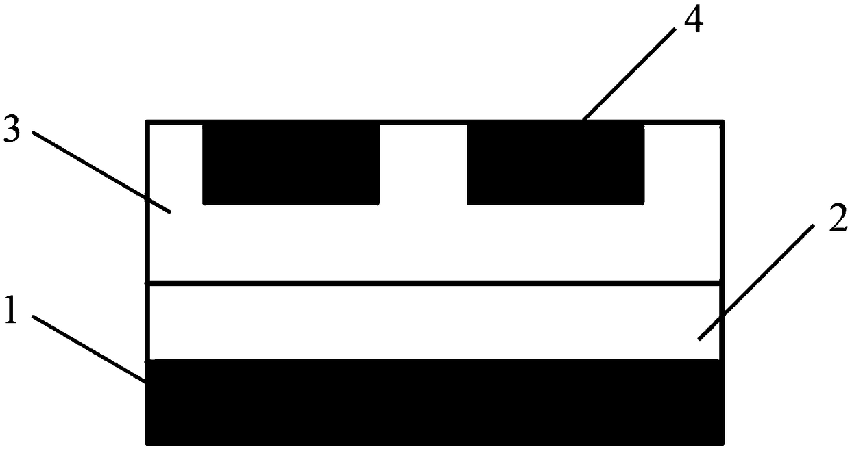
[0032] Such as figure 1 As shown, it is an optical filter structure of this embodiment, which is composed of a base layer 1, a control layer 2 and a dielectric layer 3 sequentially connected from bottom to top. The dielectric layer 3 is embedded with two rectangular metal nanoblocks 4, and the metal nano The upper surface of the block 4 is equal to the upper surface of the dielectric layer 3, the lower surface of the metal nano block 4 is higher than the lower surface of the dielectric layer 3, and the control layer 2 is VO 2 Thin films, metal nanoblocks 4 are made of noble metal materials.

[0033] Specifically: the metal nano-block 4 is made of a noble metal material, which can be one of gold and silver, and is preferably gold in this embodiment. The base layer 1 is a glass substrate, and the dielectric layer 3 is made of a transparent insulating material, preferably PMMA in this embodiment. The thickness of the dielectric layer 3 is 40-100 nm.

[0034] Specifically: in t...

Embodiment 2

[0038] Based on the optical filter structure disclosed in Embodiment 1, this embodiment discloses an optical filter by adjusting the length of the two rectangular metal nano-blocks 4 and the boundary between the two rectangular metal nano-blocks 4 and the dielectric layer 3 in this embodiment. The distance between them, their transmission characteristics and the change of the electric field.

[0039] Such as figure 1 As shown, when the two rectangular metal nano-blocks 4 are both 50nm long, the distance between the two rectangular metal nano-blocks 4 is 50nm, and the distance between the two rectangular metal nano-blocks 4 and the boundary of the dielectric layer 3 is 50nm, that is, the dielectric layer 3 The length is 250nm.

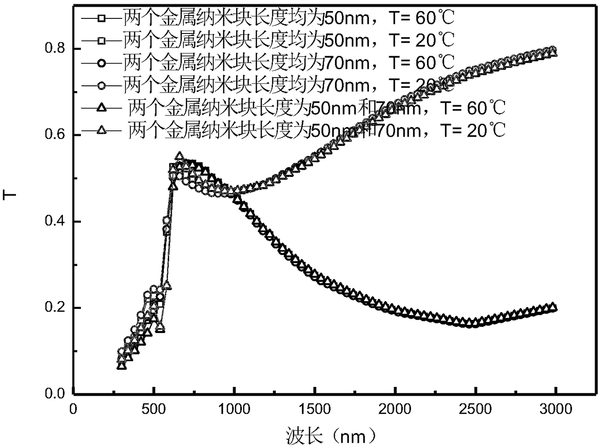
[0040] Such as figure 2 For the two transmission spectrum curves of the optical filter structure whose length of the dielectric layer 3 is 250nm, it is figure 2The transmission spectrum of the optical filter structure shown in the figure can be see...

Embodiment 3

[0043] Based on the optical filter disclosed in Embodiment 2, this embodiment discloses an optical filter. The difference from Embodiment 2 is that in this embodiment, such as figure 1 As shown, the length of the two rectangular metal nano-blocks 4 is 50nm, the distance between the two rectangular metal nano-blocks 4 is 50nm, and the distance between the two rectangular metal nano-blocks 4 and the boundary of the dielectric layer 3 is 75nm, that is, the distance of the dielectric layer 3 The length is 300nm.

[0044] In this embodiment, VO 2 The phase transition can be achieved by changing the temperature, so that VO 2 The lattice structure can be changed from tetragonal rutile structure (T>60°C) to monoclinic structure (T<60°C) or vice versa, so as to realize the change of regulated optical properties.

[0045] from figure 2 It can be seen in the figure that the filtering effect of the optical filter whose length of the dielectric layer 3 is changed to 300nm is the same a...


PUM

PropertyMeasurementUnit
Thicknessaaaaaaaaaa
Lengthaaaaaaaaaa
Phase transition temperatureaaaaaaaaaa

Abstract

The invention relates to an optical device in particular to an optical filter structure, a preparation method thereof and a method for adjusting transmission characteristics thereof. The optical filter structure is formed by successively connecting a base layer, a control layer and a dielectric layer from bottom to top. Two rectangular metal nanometer blocks are embedded in the dielectric layer. The upper surfaces of the metal nanometer blocks are flush with the upper surface of the dielectric layer. The lower surfaces of the metal nanometer blocks are higher than the lower surface of the dielectric layer. The control layer is a VO2 film. The metal nanometer blocks are made of a precious metal material. The phase change of the control layer is achieved by controlling the ambient temperature of the optical filter structure, thereby changing the transmission characteristics of the optical filter structure, achieving broadband transmission, and adjusting the broadband transmission intensity and a local electric field enhanced position in the middle-infrared band. The optical filter structure is simple and convenient in preparation and use method and is easy to operate.

Description

technical field [0001] The invention belongs to the technical field of optical devices, and in particular relates to an optical filter structure, a preparation method thereof, and a method for adjusting transmission characteristics. Background technique [0002] At present, researchers have studied the optical transmission properties of circular nanoholes, spheres and triangular metal nanostructures, and found that the EOT phenomenon can be formed by morphological resonance, surface plasmon resonance, and localized surface plasmon resonance. . However, the resulting EOT transmission spectrum generally exhibits a narrow transmission peak, which limits its application. Contents of the invention [0003] In order to solve the problem of the narrow ETO transmission peak existing in the prior art, the embodiment of the present application provides an optical filter structure and its preparation method and a method for adjusting the transmission characteristics. The embodiment ...

Claims


Application Information

Patent Timeline
IPC IPC(8): G02B5/20G02F1/01
CPCG02B5/20G02F1/0147
Inventor 不公告发明人
Owner 中山科立特光电科技有限公司
Why Eureka
Try Eureka