Dehumidifying apparatus for electric power cabinet

A power cabinet and drying device technology, which is applied in substation/distribution device shell, cooling/ventilation of substation/switchgear, details of substation/switch layout, etc., can solve the problem of large impact on safe operation, large economic burden, power equipment, etc. Solve problems such as terminal corrosion, and achieve the effect of being suitable for promotion and production, strong drying and water absorption, and remarkable dehumidification effect

Inactive Publication Date: 2018-12-07
陈镜明
View PDF0 Cites 3 Cited by
  • Summary
  • Abstract
  • Description
  • Claims
  • Application Information

AI Technical Summary

Problems solved by technology

[0002] In the power system, air humidity has a great influence on the safe operation of electrical equipment. In the prior art, desiccant is generally used for dehumidification, or the door of the cabinet is opened and closed for ventilation and heat dissipation. The dehumidification effect is poor and is greatly affected by the external environment. High humidity will cause a short circuit in the line, which will cause immeasurable losses to the power company. If the power cabinet operates in a humid environment, it will bring hidden dangers to its safety, especially when the temperature difference is large, it will cause condensation. It will cause corrosion of the terminals of the power equipment, reduce the insulation performance and cause a short circuit, resulting in undue power outages and losses. If you use a dehumidifier, the power of the dehumidifier is too large, and the machine will work continuously, which will cause great economic losses. Burden; if the equipment fails, if the humidity in the power cabinet is high, there may be a risk of electric shock if the maintenance personnel directly open the power cabinet

Method used


Image

  • Dehumidifying apparatus for electric power cabinet

Examples


Embodiment Construction

[0012] The following will clearly and completely describe the technical solutions in the embodiments of the present invention with reference to the accompanying drawings in the embodiments of the present invention. Obviously, the described embodiments are only some, not all, embodiments of the present invention. Based on the embodiments of the present invention, all other embodiments obtained by persons of ordinary skill in the art without making creative efforts belong to the protection scope of the present invention.

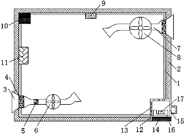
[0013] The present invention provides such figure 1 The dehumidification device for a power cabinet shown includes a cabinet body 1, and a temperature insulation board 2 is provided outside the cabinet body 1, and the temperature insulation board 2 is a vacuum temperature insulation board, and the left lower part of the cabinet body 1 is An air inlet 3 is provided, the left end of the air inlet 3 is provided with a filtering device 4, the middle part of the ai...


PUM


Abstract

The invention discloses a dehumidifying apparatus for an electric power cabinet. The dehumidifying apparatus for an electric power cabinet comprises a cabinet body, wherein an air inlet is arranged atthe lower part of the left side of the cabinet body; a filtering device is arranged at the left end of the air inlet; a drying device is arranged at the middle part of the air inlet; the right end ofthe air inlet is communicated with an air outlet end of an air heater; an air outlet is arranged at the upper part of the right side of the cabinet body; the left end of the air outlet is communicated with an air inlet end of an exhaust fan; a humidity sensor is arranged at the top end in the cabinet body; a controller is arranged at the upper end of the left side in the cabinet body; a relay isarranged at the left side in the cabinet body; the filtering device and the drying device are arranged at the air inlet, thus guaranteeing that the inlet air has no fine particles and is dry; the airheater can heat the air at the source, thus preventing the condensation phenomenon, and a thermal insulating plate can also prevent the condensation phenomenon; and allochroic silica gel has strong drying and water absorption effect. The dehumidifying apparatus for an electric power cabinet has the advantages of being reasonable in design, being low in cost, and being suitable for promotion and production.

Description

technical field [0001] The invention belongs to the technical field of power systems, and in particular relates to a dehumidification device for a power cabinet. Background technique [0002] In the power system, air humidity has a great influence on the safe operation of electrical equipment. In the prior art, desiccant is generally used for dehumidification, or the door of the cabinet is opened and closed for ventilation and heat dissipation. The dehumidification effect is poor and is greatly affected by the external environment. High humidity will cause a short circuit in the line, which will cause immeasurable losses to the power company. If the power cabinet operates in a humid environment, it will bring hidden dangers to its safety, especially when the temperature difference is large, it will cause condensation. It will cause corrosion of the terminals of the power equipment, reduce the insulation performance and cause a short circuit, resulting in undue power outages ...

Claims


Application Information

Patent Timeline
Patent Type & Authority Applications(China)
IPC IPC(8): H02B1/56H02B1/28
CPCH02B1/565H02B1/28
Inventor 陈镜明
Owner 陈镜明
Why Eureka
Try Eureka