A method for predicting fluid temperature distribution in a vertical U-shaped buried pipe of a ground source heat pump under off-design conditions

A fluid temperature, ground source heat pump technology, applied in heat recovery systems, energy-saving heating/cooling, instruments, etc.

Active Publication Date: 2018-12-25
ANHUI UNIVERSITY OF TECHNOLOGY
View PDF2 Cites 14 Cited by
  • Summary
  • Abstract
  • Description
  • Claims
  • Application Information

AI Technical Summary

Problems solved by technology

However, the above three literatures are all based on the linear heat source model, so there is a large error in predicting the temperature field in a short time
[0009] ...

Method used


Image

  • A method for predicting fluid temperature distribution in a vertical U-shaped buried pipe of a ground source heat pump under off-design conditions
  • A method for predicting fluid temperature distribution in a vertical U-shaped buried pipe of a ground source heat pump under off-design conditions
  • A method for predicting fluid temperature distribution in a vertical U-shaped buried pipe of a ground source heat pump under off-design conditions

Examples


Embodiment 1

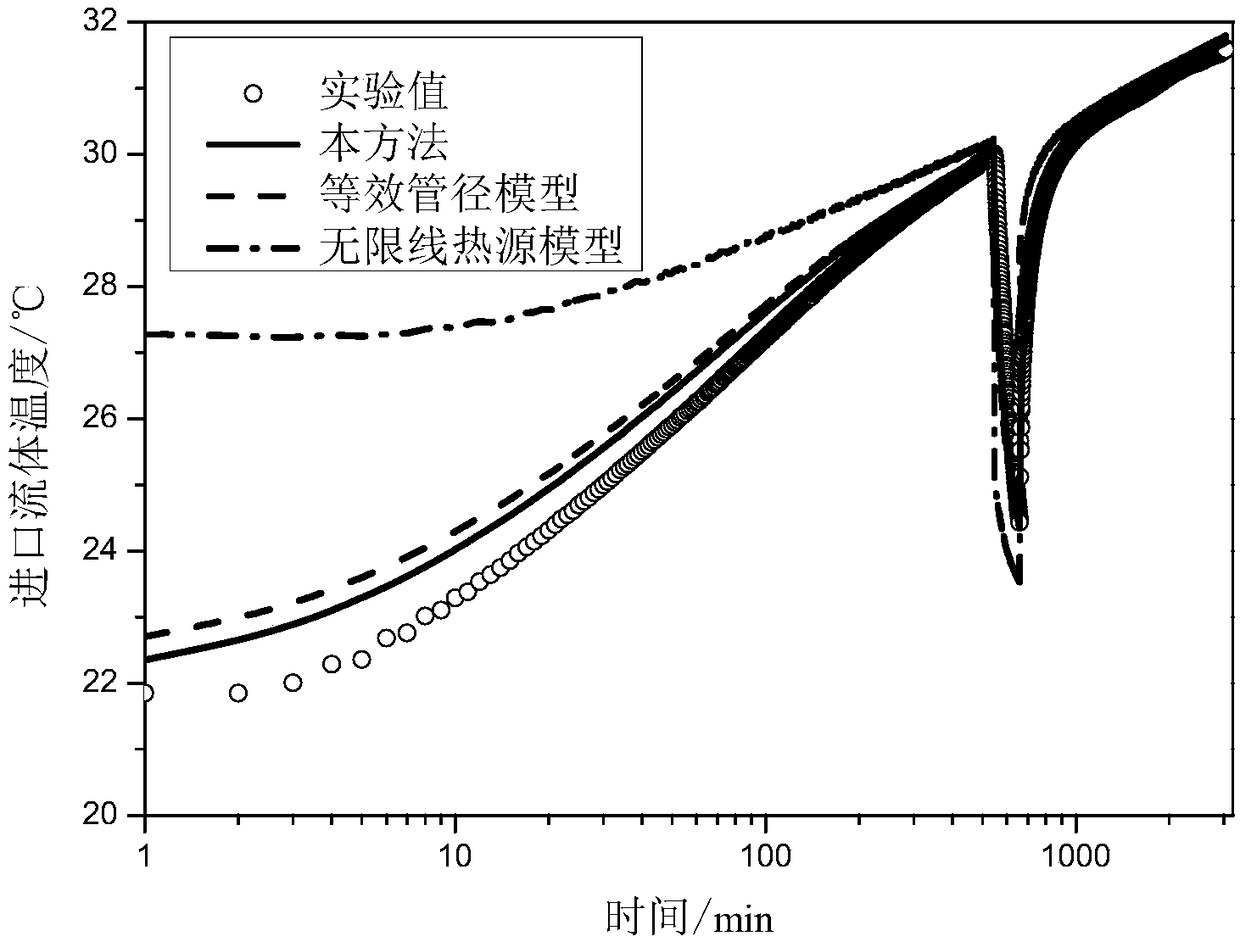
[0136] This embodiment is aimed at the sandbox experiment under the variable heat flow condition completed by Professor Beier of the United States in 2011, and provides a prediction method for the fluid temperature distribution under the variable heat flow Q(t) condition, and compares the calculated inlet and outlet fluid temperatures with the experimental value Comparing with other model results, the fluid temperature distribution is calculated at the same time.

[0137] By simulating the actual thermal response test, the sandbox experiment was carried out in a room with constant temperature, the sandbox was placed horizontally in the room, and the U-shaped pipe and backfill were placed horizontally in the center of the sandbox. The electric heater is used to heat the fluid, and at the same time, the fluid is driven to circulate in the U-shaped tube, and the inlet and outlet fluid temperature, heat flow, mass flow, etc. are recorded every minute. The experiment lasts 3038 minu...

Embodiment 2

[0153] This embodiment is aimed at the sandbox experiment under the constant heat flow condition completed by Professor Beier of the United States in 2011, and calculates the fluid temperature distribution under the constant heat flow Q(t) condition, and compares the calculated inlet and outlet fluid temperatures with the experimental values ​​and other models The results are compared.

[0154] This experiment is basically the same as the experiment in Example 1, except that the heat flow, mass flow rate and experiment duration are different. The duration of the experiment is 3106 minutes, and the heat flow does not change with time.

[0155] The specific steps of this embodiment are the same as those of Embodiment 1.

[0156] The comparison of the calculated inlet and outlet fluid temperatures with the experimental values ​​and other model results are as follows: Figure 7 with Figure 8 As shown, the comparison between this method and the absolute error of the inlet and o...

Embodiment 3

[0161] This embodiment provides the variable inlet fluid temperature T for the sandbox experiment under the condition of variable inlet fluid temperature completed by Professor Beier of the United States in 2011. in (t) The prediction method of fluid temperature distribution under working conditions, and compare the calculated heat flow and outlet fluid temperature with the experimental value, and calculate the fluid temperature distribution at the same time. This experiment is exactly the same as the experiment in embodiment 2, and the difference between this embodiment and embodiment 2 is as follows: embodiment 2 calculates the inlet and outlet fluid temperature under the condition of known constant heat flow, and this embodiment is known Variable inlet fluid temperature T in Calculate the heat flow and outlet fluid temperature under the condition of (t).

[0162] The concrete steps of this embodiment are as follows:

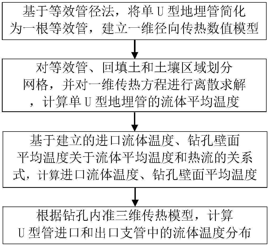
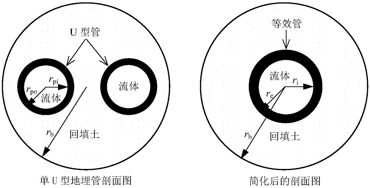
[0163] Step 1: If figure 2 As shown, the single U-sh...


PUM


Abstract

A method for predicting fluid temperature distribution of a vertical single U-shaped buried pipe of a ground source heat pump under variable operating conditions belongs to that field of ground sourceheat pump, and is used for calculating fluid temperature distribution in U-shaped pipe under variable heat flux or variable inlet fluid temperature operating conditions. Firstly, a single U-shaped buried pipe is simplified to an equivalent pipe based on the equivalent pipe diameter method, and a one-dimensional radial heat transfer numerical model including fluid, equivalent pipe, backfill and soil is established, and the heat transfer equation is discretely solved to calculate the average temperature of the fluid in the single U-shaped buried pipe. The results show that the average temperature of the fluid in the U-shaped buried pipe is higher than that in the single U-shaped pipe. Then, based on the quasi-three-dimensional heat transfer model in the borehole, the relationship between the inlet fluid temperature and the average wall temperature of the borehole with respect to the average fluid temperature and heat flux is established, and the fluid temperature distribution in the U-tube under the conditions of variable heat flux or variable inlet fluid temperature is calculated. This method has the advantages of less computation, high precision and strong generality.

Description

technical field [0001] The invention relates to the technical field of ground source heat pumps, in particular to a method for predicting the fluid temperature distribution of a vertical single U-shaped underground pipe of a ground source heat pump under variable working conditions, which is used to calculate the fluid temperature distribution in the U-shaped pipe under variable heat flow or variable inlet fluid temperature conditions. fluid temperature distribution. Background technique [0002] Ground source heat pumps have developed rapidly in recent decades and have become the main form of utilization of geothermal energy. Among them, the vertical single U-shaped underground pipe ground source heat pump has more prominent advantages, and is currently the most widely used ground source heat pump. [0003] The prediction method of fluid temperature distribution in buried pipes is an important content of ground source heat pump research, and has been widely used in ground ...

Claims


Application Information

Patent Timeline
IPC IPC(8): G06F17/50
CPCG06F2111/10G06F2119/08G06F30/20Y02B30/52Y02E10/10
Inventor 王昌龙黄志甲钱付平鲁月红唐刚
Owner ANHUI UNIVERSITY OF TECHNOLOGY
Why Eureka
Try Eureka