Automatic reeling equipment

A roll material, automatic technology, applied in the direction of coiling strips, thin material processing, transportation and packaging, etc., can solve the problems of low efficiency and high labor intensity of workers, and achieve high connection strength, simple structure, reasonable and compact layout Effect

Pending Publication Date: 2019-01-22
XIAMEN ZHENGLIMING METALLURGICAL MACHINERY
View PDF2 Cites 5 Cited by
  • Summary
  • Abstract
  • Description
  • Claims
  • Application Information

AI Technical Summary

Problems solved by technology

The existing coiling equipment has the following disadvantages: first, it is necessary to manually position the material head of the sheet on the

Method used


Image

  • Automatic reeling equipment
  • Automatic reeling equipment
  • Automatic reeling equipment

Examples


Embodiment Construction

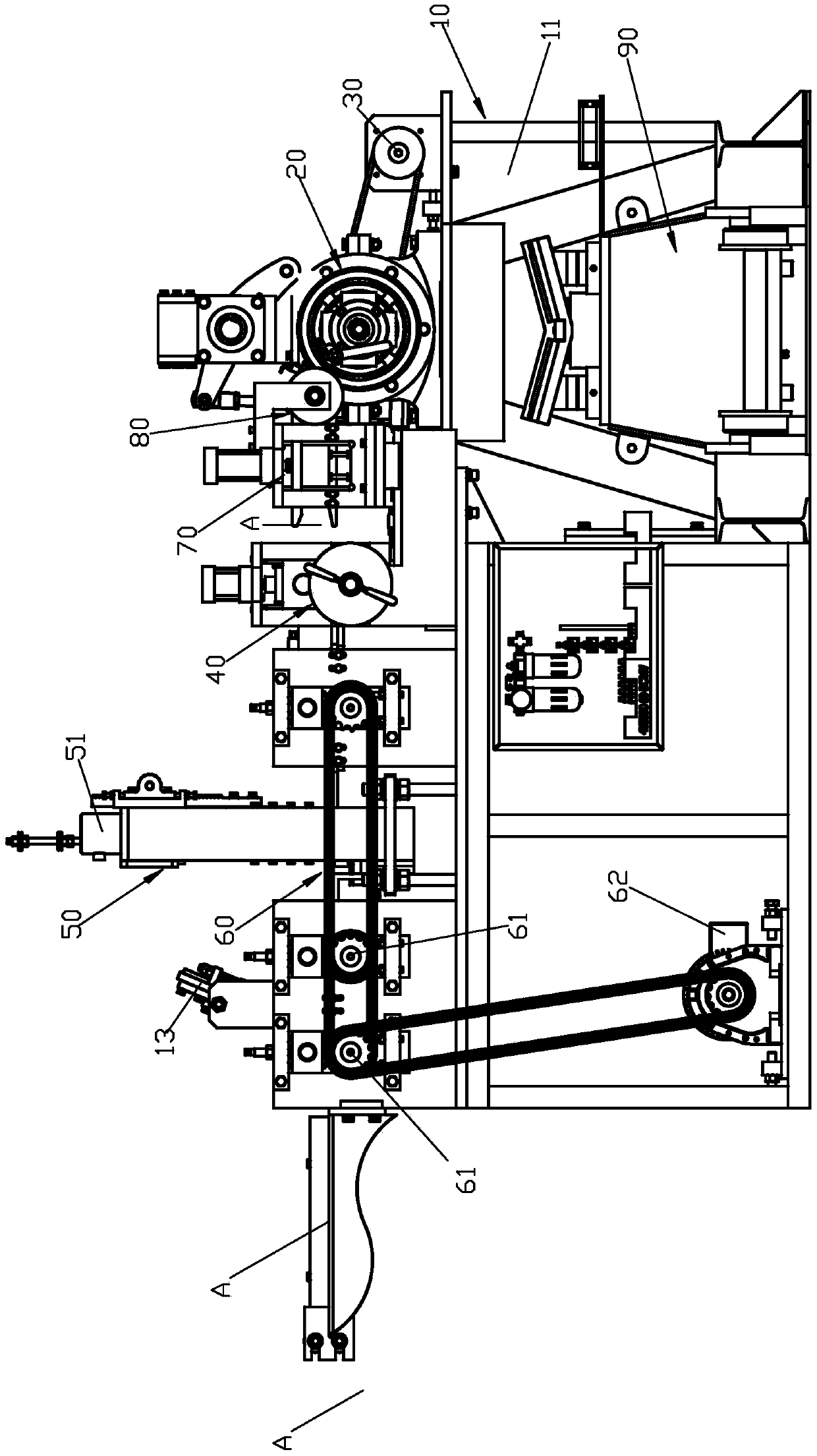
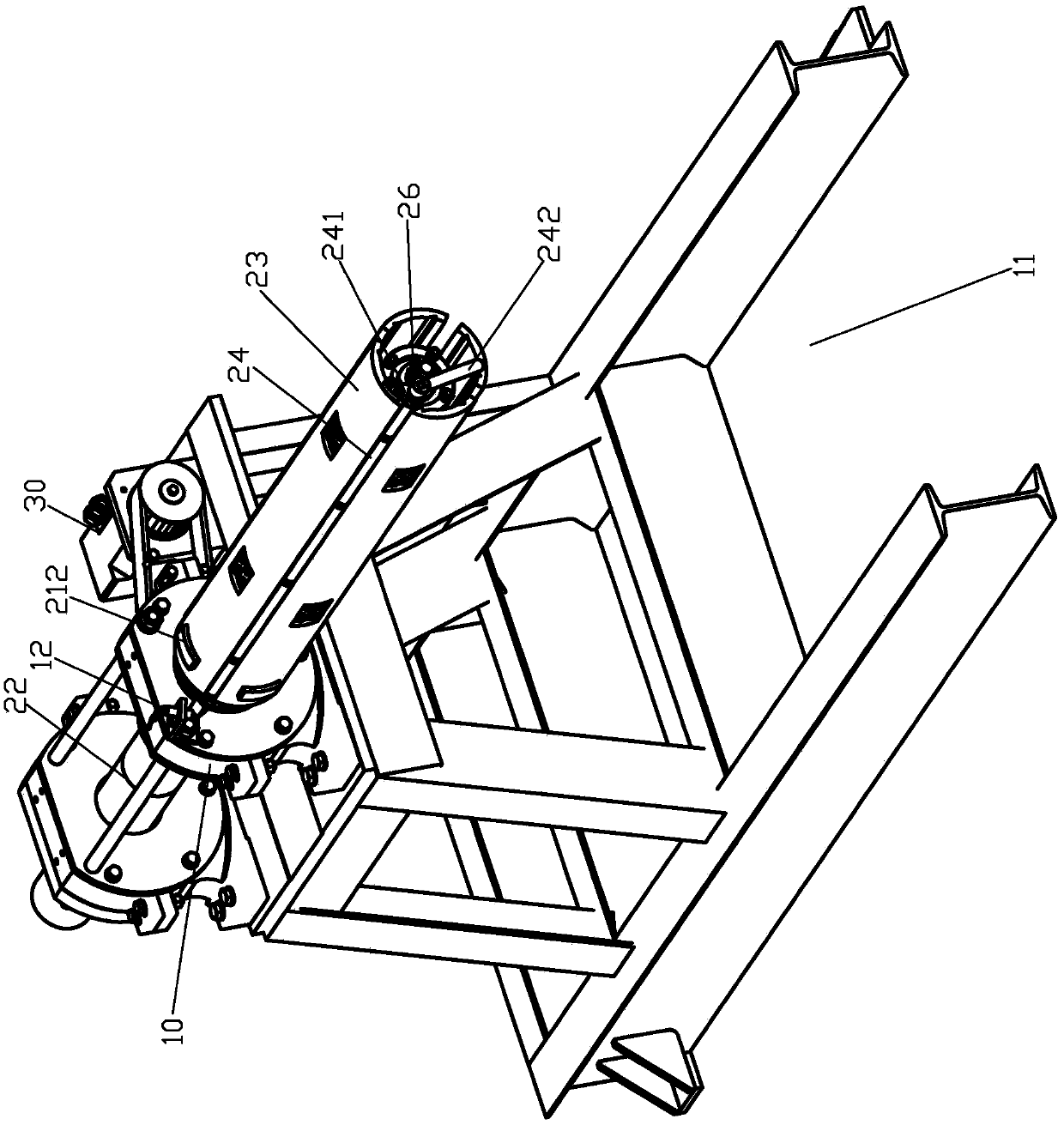
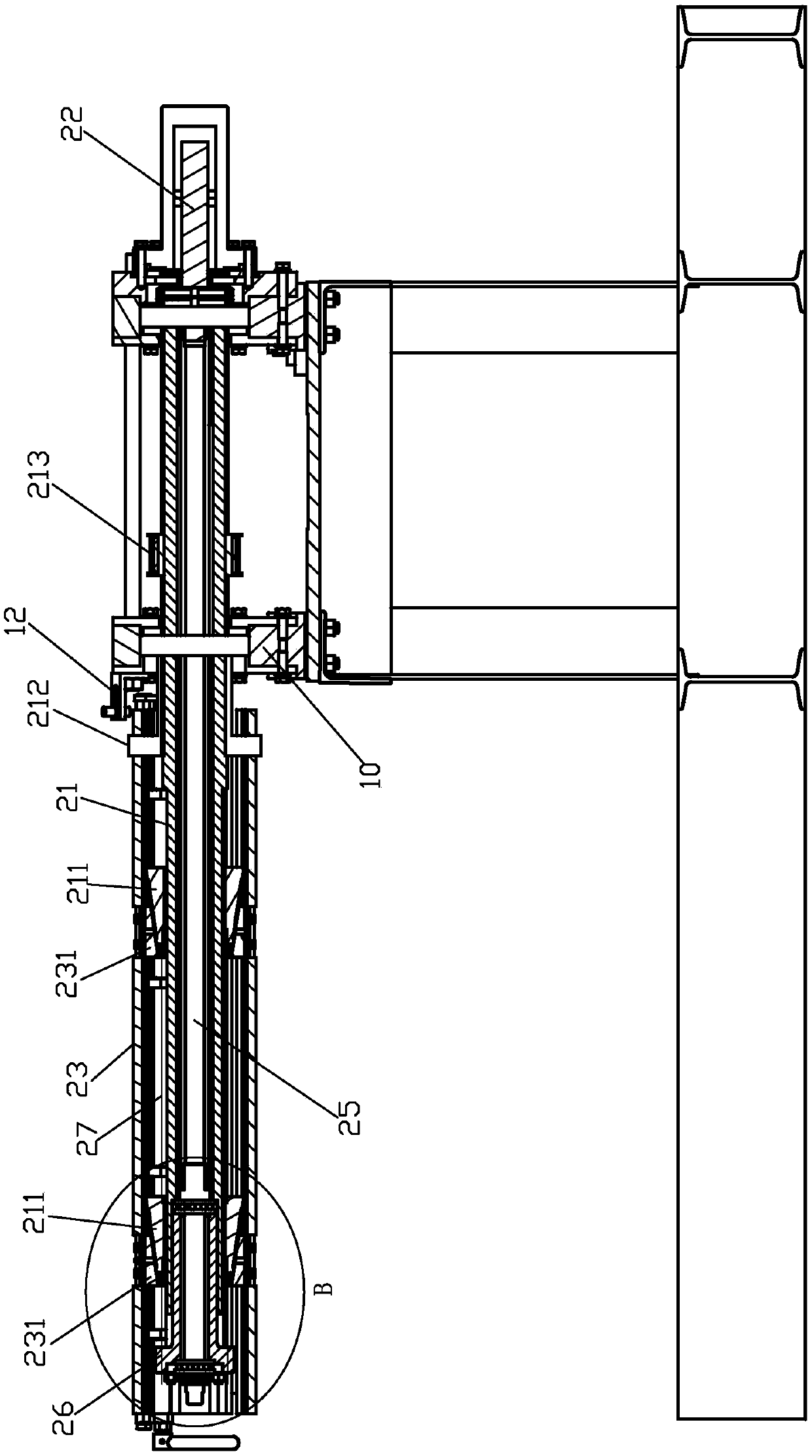
[0040] Please check Figure 1 to Figure 10 , automatic coiling equipment, including a frame 10, a coiling device, a first driver 30, a tensioning mechanism 40, a shearing mechanism 50, and a conveying mechanism 60. The coiling device includes a coiling mechanism 20 , a material leading device 70 and a guiding device 80 .

[0041] The coil mechanism 20 includes a support shaft 25, a rotating part, a second driver 22 and a clamping head mechanism. The rotating part includes a main shaft 21 and a plurality of circular arrays arranged at intervals around the main shaft 21 and capable of radially moving relative to the main shaft 21. part 23, the movable part 23 is an arc-shaped plate; the main shaft 21 is rotatably mounted on the frame 10 and rotatably sleeved outside the support shaft 25; the movable part 23 and the main shaft 21 form a synchronous The rotating and movable part 23 can be connected radially relative to the main shaft 21 . The first driver 30 is connected to the ...


PUM


Abstract

The invention discloses automatic reeling equipment, comprising a reeling mechanism and a first driver. The reeling mechanism comprises a rotation unit, a second driver and a material-end clamping mechanism; the rotation unit comprises a plurality of moving units capable of doing radial movement relative to the rotation axis of the rotation unit; the first driver is in drive connection with the rotation unit to drive the same to rotate to reel a sheet material automatically, thereby improving reeling efficiency and uniformity while reducing labor cost. The material-end clamping mechanism comprises clamping units capable of moving between a clamping position and a loosening position relative to the moving units; the clamping units at the clamping position are matched with the moving units to clamp a sheet material end, and the clamping units at the loosening position can release the clamping, thereby facilitating clamping of the material end and removing the inconvenience in moving thematerial end manually.

Description

technical field [0001] The invention relates to a material rewinding device, in particular to a material rewinding device capable of automatically rewinding sheet materials. Background technique [0002] Existing coiling equipment, such as CN205274869U, CN207001786U, etc., includes a frame and a coiling mechanism; the coiling mechanism includes a rotating part, and the rotating part includes several circumferentially spaced parts that are arranged around the axis of rotation of the rotating part and can rotate relatively The movable part whose rotation axis moves radially can control the radius of the circumferential arrangement of the movable part through the radial movement of the movable part. It can control the movable part to abut against the inner hole wall of the coiled sheet or release the abutment, and control the loosening of the rolled sheet. The existing coiling equipment has the following disadvantages: firstly, it is necessary to manually position the head of ...

Claims


Application Information

Patent Timeline
IPC IPC(8): B65H18/10B65H75/28
CPCB65H18/10B65H75/285
Inventor 黄溢忠何昌甫苏洲洲陈运水
Owner XIAMEN ZHENGLIMING METALLURGICAL MACHINERY
Why Eureka
Try Eureka