High power diesel vehicle hydraulic brake inertia booster

A diesel vehicle, hydraulic braking technology, applied in the direction of brakes, brake transmission devices, control devices, etc., can solve problems such as waste of fuel, and achieve the effect of reducing the action time

Active Publication Date: 2021-04-30
翟正环
View PDF4 Cites 0 Cited by
  • Summary
  • Abstract
  • Description
  • Claims
  • Application Information

AI Technical Summary

Problems solved by technology

[0007] Another disadvantage of air braking systems is the waste of fuel

Method used


Image

  • High power diesel vehicle hydraulic brake inertia booster
  • High power diesel vehicle hydraulic brake inertia booster

Examples


Embodiment Construction

[0027] The technical solution of the present invention will be further described below in conjunction with the accompanying drawings, but it should not be understood as a limitation on the technical solution, and equivalent improvements on this basis all belong to the protection scope of the present invention.

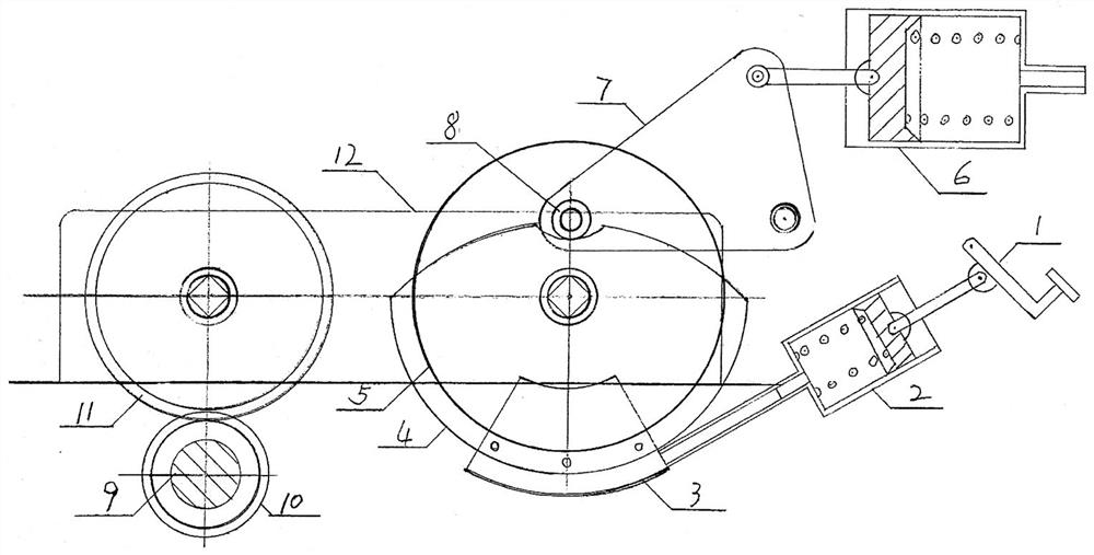
[0028] Such as figure 1 As shown, the high-power diesel vehicle hydraulic brake inertia booster includes a brake pedal 1, a brake master cylinder 2, a brake caliper 3, a cam disc 4, an inertia disc 5, a booster pump 6, a triangular plate lever 7, a roller 8, Automobile transmission shaft 9, transmission shaft gear 10 and speed reducer 12, fix a bracket to install speed reducer 12 on the upper part of the automobile rear axle, and fix a transmission shaft gear 10 in series in the universal joint that automobile transmission shaft 9 and rear axle are connected, speed reducer The reducer input gear 11 of 12 meshes with the transmission shaft gear 10 on the automobile driv...


PUM


Abstract

The invention discloses a high-power diesel automobile hydraulic braking inertia booster, a fixed reducer (12) on the rear axle of the automobile, an automobile drive shaft (9) connected in series with the drive shaft gear (10), and the reducer input gear (11) meshing with the drive shaft Gear (10), the inertia disc (5) is installed on the output shaft of the reducer and the cam disc (4) is suspended, the brake caliper (3) is fixed on the lower part of the cam disc (4), and the inertia disc (5) is put into the brake caliper ( 3) In the mouth, the brake caliper (3) is connected to the piston of the master cylinder (2), the connecting rod of the piston of the master cylinder (2) is connected to the brake pedal (1), and the roller is installed in the groove of the cam disc (4) ( 8), the top corner of the triangular plate lever (7) is fixed on the roller (8), the bottom corner of the triangular plate lever (7) is connected to the booster pump (6) piston ejector rod, and the piston of the triangular plate lever (6) is connected to the brake cylinder. The invention has sufficient power source to provide brake braking, flexible forward and backward braking, no fuel consumption for braking, and good braking efficiency and safety factor.

Description

technical field [0001] The invention relates to auto parts, in particular to a hydraulic braking inertia booster for a high-power diesel automobile. Background technique [0002] Large and medium-sized passenger and freight vehicles are all diesel vehicles with pneumatic brakes. When the pneumatic brake system is braking, the high-pressure gas in the air storage tank must be quickly charged into the brake sub-chamber, so that the camshaft supports the brake shoes and the braking system. Dynamic drum friction braking, the air pressure in the brake sub-chamber rises from zero to 8kg / cm 2 The above will take a certain amount of time to be sufficient. Before the camshaft supports the brake shoe, it is necessary to overcome the 125kg pulling force of the two brake shoe return springs before squeezing the brake shoe and the brake drum for frictional braking, which also takes a certain amount of time. [0003] The time from depressing the brake pedal to the friction between the b...

Claims


Application Information

Patent Timeline
Patent Type & Authority Patents(China)
IPC IPC(8): B60T13/06B60K25/06
CPCB60K25/06B60T13/06
Inventor 翟正环翟笑崧翟度天
Owner 翟正环
Why Eureka
Try Eureka