
Pericardial effusion assisted drainage device
A technology for pericardial effusion and fluid inflow, which is applied in the field of auxiliary drainage devices for pericardial effusion, can solve the problem of inconvenient input of physiological saline, and achieves the effect of reducing workload and reducing pain.
- Summary
- Abstract
- Description
- Claims
- Application Information
AI Technical Summary
Problems solved by technology
Method used
Image

Examples
Embodiment
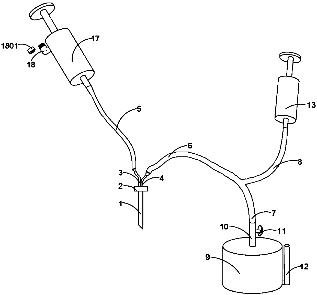
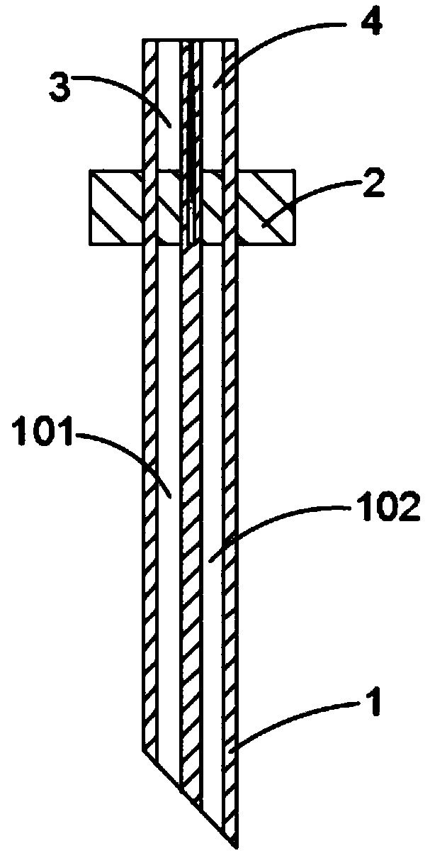
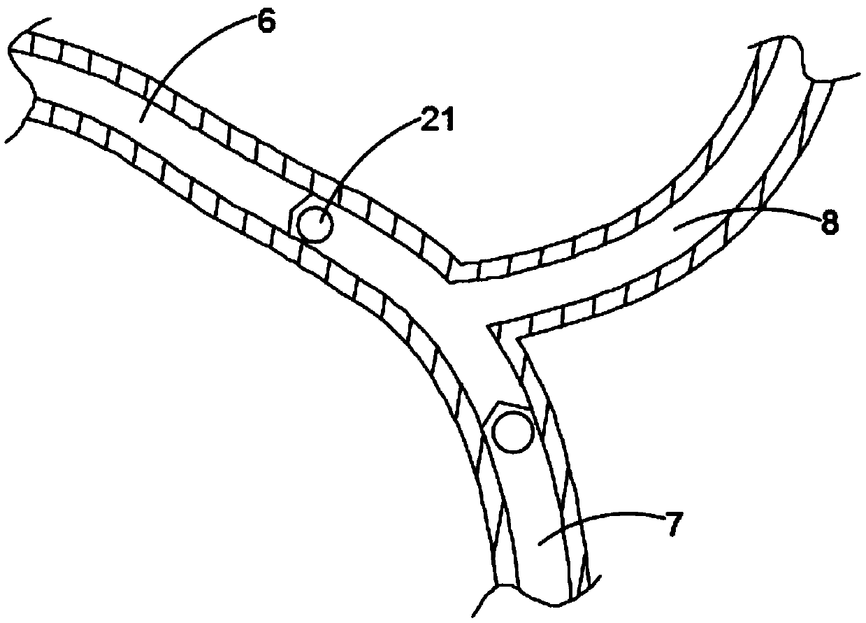
[0031] A kind of pericardial effusion auxiliary drainage device of the present embodiment, refer to Figure 1-5 : including a puncture needle 1 and a liquid storage tank 9, a connection handle 2 is arranged on the upper part of the outer wall of the puncture needle 1, and a liquid inlet cavity 101 and a liquid outlet cavity 102 are opened in the needle body of the puncture needle 1, and the liquid inlet cavity 101 The liquid inlet connecting pipe 3 and the liquid outlet connecting pipe 4 are respectively connected with the top port of the liquid outlet inner cavity 102; the other ends of the liquid inlet connecting pipe 3 and the liquid outlet connecting pipe 4 are respectively connected with a liquid inlet conduit 5 and a Y-shaped conduit 6-way, the other end of the Y-shaped conduit 6 communicates with the catheter tube 7 and the air guide tube 8 respectively, and the inner chambers of the Y-shaped conduit 6 and the catheter tube 7 are respectively provided with a one-way valv...
PUM
 Abstract
Description
Claims
Application Information