A step-by-step pressurized pneumatic infusion device

A technology of an infusion device and an air outlet, which is applied in the field of medical devices, can solve the problems of large differences in blood drug concentrations, insufficient flow control accuracy, and polluted ambient air.

Active Publication Date: 2021-04-30
ZHEJIANG NORMAL UNIVERSITY
View PDF6 Cites 0 Cited by
  • Summary
  • Abstract
  • Description
  • Claims
  • Application Information

AI Technical Summary

Problems solved by technology

This infusion mode will bring many problems in actual use: the flow rate is adjusted manually, and the flow control accuracy is not enough; the infusion bottle needs to be held high by others when the patient walks or goes to the toilet, which is inconvenient to move and the height of the infusion bottle is not high enough. Make the blood flow back; patients or nurses need to be guarded for a long time, if the infusion is not found in time, it may cause accidents; the liquid medicine is in contact with the air, and the ambient air may be polluted when the air is unclean
In addition to the above direct problems, sometimes the infusion time is shortened by reducing the amount of solution, speeding up the infusion speed, etc., which not only increases the burden on the heart, but also affects the therapeutic effect: intramuscular injection and subcutaneous injection in a relatively short period of time. The biggest disadvantage of injecting into muscle or subcutaneous is that the blood drug concentration varies greatly within an injection cycle, which is not conducive to the effective absorption and utilization of drugs, because most drugs have a better concentration range in the human body, and when the drug concentration is too high Has toxic side effects, if it is too low, it will have no therapeutic effect

Method used


Image

  • A step-by-step pressurized pneumatic infusion device
  • A step-by-step pressurized pneumatic infusion device
  • A step-by-step pressurized pneumatic infusion device

Examples


Embodiment Construction

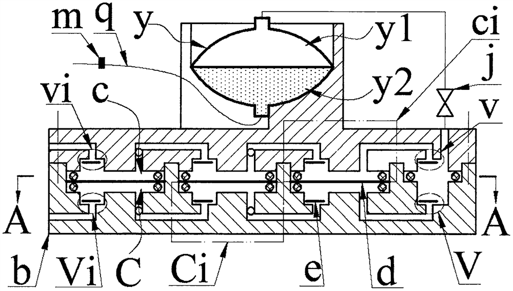
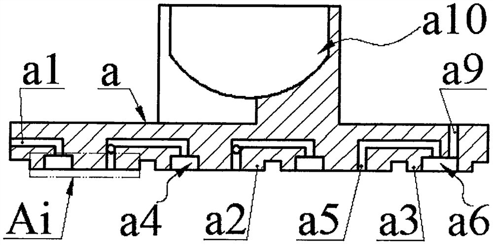
[0015] The bottom of the main body a is provided with an upper inlet hole a1, a boss a3 with an upper outlet cavity a6 and an outlet hole a9, and at least two round platform groups Ai. The number decreases in turn; one round table a2 in each round table group Ai is provided with an upper inlet a4 and an upper air outlet a5, and the other round tables a2 are only provided with an upper air hole a8; The inlet hole a1 is connected, and the upper air outlet a5 in the rightmost round platform group Ai is connected with the outlet hole a9 through the upper outlet opening a6; the upper air outlet a5 and the upper ventilation hole a8 in the same round platform group Ai are connected through the upper communication hole a7, The upper inlet a4 and the upper air outlet a5 in the two left and right adjacent round table groups Ai are connected; the upper inlet a4 and the upper outlet a6 form the upper inlet valve vi and the upper outlet valve v respectively with the upper inlet a4 and the u...


PUM


Abstract

The invention relates to a step-by-step pressurized pneumatic infusion device, which belongs to the field of medical equipment. The main body is provided with an upper inlet hole, a boss with an upper outlet cavity and an outlet hole, and at least two round table groups whose number of round tables changes sequentially; one round table in the round table group is provided with an upper inlet mouth and an upper air outlet, and the other round tables are provided. There is an upper ventilation hole; the body cavity is equipped with an infusion bag with an air cavity and a medicine cavity, and the air cavity is connected to the outlet hole; the base is provided with a lower inlet hole, a cavity with a lower outlet mouth, and a body cavity group composed of a body cavity; the body cavity One of the body cavities in the group is provided with a lower inlet and a lower air hole, and the other body cavities are equipped with a lower air hole; the upper and lower inlet and outlet chambers and the valve plates inside constitute the upper and lower inlet and outlet valves; the main body is installed on the base so that the upper and lower outlets and the outlet The holes are connected, and the piezoelectric driver is crimped into the body cavity through the sealing ring to form the upper and lower compression chambers. The upper and lower compression chambers in the same body cavity group are connected in parallel to form the upper and lower compression chamber groups, and the upper and lower compression chamber groups are connected in series to form parallel upper and lower compression chambers. unit.

Description

technical field [0001] The invention belongs to the field of medical devices, and in particular relates to a step-by-step pressurized pneumatic infusion device. Background technique [0002] Injection mainly includes intravenous injection, intramuscular injection and subcutaneous injection. Intravenous injection is also called infusion drug administration. Most of the existing infusion devices are composed of infusion bottles, infusion tubes and infusion stands. This infusion mode will bring many problems in actual use: the flow rate is adjusted manually, and the flow control accuracy is not enough; the infusion bottle needs to be held high by others when the patient walks or goes to the toilet, which is inconvenient to move and the height of the infusion bottle is not high enough. Make the blood flow back; the patient or the nursing staff need to watch for a long time, if the infusion is not found in time, it may cause an accident; the liquid medicine is in contact with th...

Claims


Application Information

Patent Timeline
Patent Type & Authority Patents(China)
IPC IPC(8): A61M5/155A61M5/168
Inventor 郑佳佳任泽峰徐晨阳苏玲马继杰王淑云曾平
Owner ZHEJIANG NORMAL UNIVERSITY
Why Eureka
Try Eureka