a power generation system

A technology of generators and DC generators, which is applied to the control system, control of generators, and control of generators through magnetic field changes. It can solve problems such as unstable work, reduced reliability, and unrealistic problems, achieving high overall utilization and Cost-effective, easy-to-control effects

Active Publication Date: 2020-09-11
CHINA JILIANG UNIV
View PDF5 Cites 0 Cited by
  • Summary
  • Abstract
  • Description
  • Claims
  • Application Information

AI Technical Summary

Problems solved by technology

[0005] The converter of the switched reluctance generator system is the heart of its work. In order to achieve different functions and different power outputs, it is often necessary to design different converter systems. The use of a large number of switching tubes, especially high-frequency switches, is extremely It greatly increases the control complexity, increases the switching loss, increases the cost, and reduces the reliability; in addition, the switched reluctance generator needs one excitation power supply when it is working. The traditional self-excitation mode has a simple structure but the output power fluctuates greatly. The work is unstable, and heavy batteries are required in the separate excitation mode, which also increases the workload of manual maintenance, and it is unrealistic to replace the batteries in the field for a long time; therefore, there is a big challenge for the introduction of switched reluctance generators into diesel generator sets , and this occasion also requires the converter system to be as simple in structure as possible, easy to control, reduce the workload of manual maintenance, minimize switching loss and improve its reliability, etc.

Method used


Image

  • a power generation system
  • a power generation system

Examples


Embodiment Construction

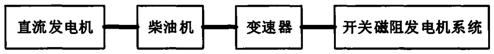
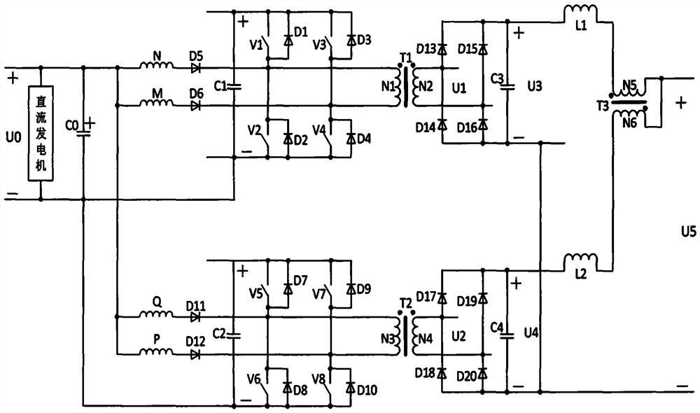
[0026] A power generation system of this embodiment, as attached figure 1 As shown in the figure, it consists of a DC generator, a diesel engine, a transmission, and a switched reluctance generator system. The DC generator, diesel engine, transmission, and switched reluctance generator system are coaxially connected. The min diesel engine generates power to rotate and run, in which the transmission is a speed increaser, and the speed is increased by 10-20 times.

[0027] The switched reluctance generator system consists of a switched reluctance generator converter, a controller and a detection device. The controller outputs a control signal to drive eight switch tubes in the switched reluctance generator converter, and the detection device detects the switched reluctance generator. In the system, various operating signals such as rotor position information, phase winding current information, and three transformer winding current information of the switched reluctance generator...


PUM


Abstract

A power generation system is composed of a DC generator, a diesel engine, a transmission and a switched reluctance generator system which are coaxially connected. The switched reluctance generator system is composed of a switched reluctance generator converter, a controller and a detection device. The detection device detects and inputs all kinds of information in the switched reluctance generatorconverter to the controller. The controller outputs a control signal to drive each switching tube in the switched reluctance generator converter. The switched reluctance generator converter is composed of eight switching tubes, twenty diodes, five capacitors, two reactors, three transformers and four phases of windings. Every two phases of windings constitute a converter synthesized with a single-phase inverter circuit for the excitation and power generation of a switched reluctance generator. Multiple AC and DC power outputs are obtained through time-sharing control on the eight switching tubes according to the position information of the rotor, and the quality of power is high. The power generation system is applicable to the field of independent power generation systems in areas without power supply.

Description

technical field [0001] The invention relates to the field of power generation systems, in particular to an independent diesel power driven switched reluctance generator system and a DC generator combined with a complementary simple multi-function converter structure and a power generation system with multiple AC and DC power outputs and a control method thereof . Background technique [0002] In some islands with no grid access, as well as field projects in uninhabited areas on plateaus and deserts, power supply is required, as well as backup power supply for some important departments in the city. Most of them use diesel-powered generator sets, but they are often Only one constant power supply can be output. [0003] The switched reluctance motor has a simple structure, low cost, no winding on the rotor, and low heat dissipation pressure. As a generator, it has considerable application value. [0004] In many applications of diesel generator sets, it is often necessary to...

Claims


Application Information

Patent Timeline
Patent Type & Authority Patents(China)
IPC IPC(8): H02P9/30H02P9/38H02P101/25
CPCH02P9/30H02P9/38H02P2101/25
Inventor 孙冠群
Owner CHINA JILIANG UNIV
Why Eureka
Try Eureka