

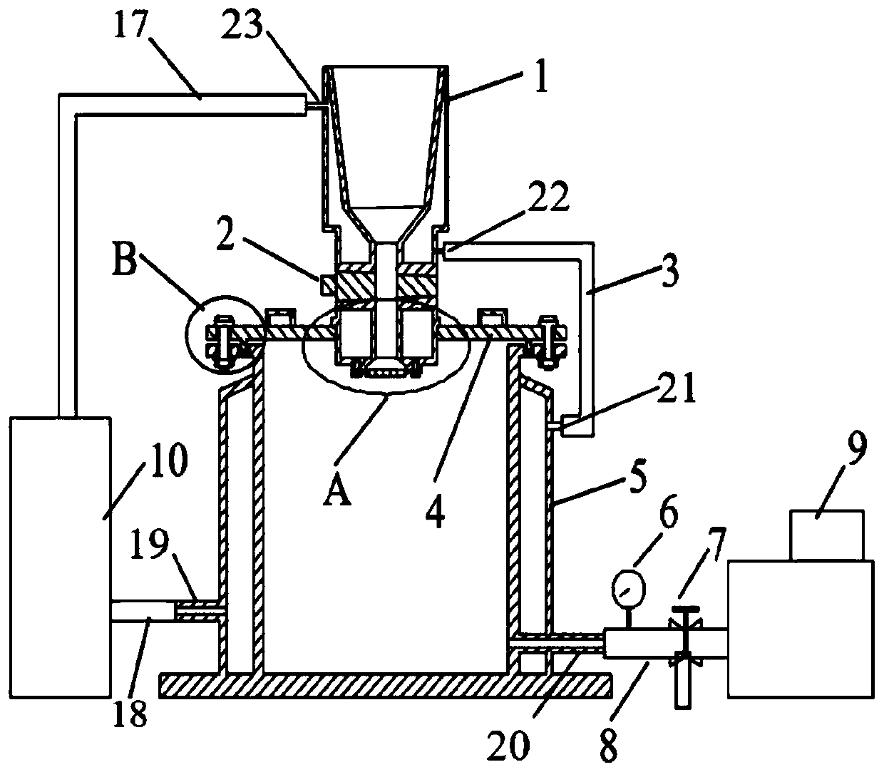
Solid fuel vacuum pouring device
A technology of vacuum casting and solid fuel, which is applied to jet propulsion devices, rocket engine devices, machines/engines, etc., can solve the problems of long intubation length, difficulty in cleaning the slurry, failure of pouring, etc., and achieves convenient installation and multi-functionality. Universality and easy disassembly
- Summary
- Abstract
- Description
- Claims
- Application Information
AI Technical Summary
Problems solved by technology
Method used
Image

Examples
Embodiment Construction
[0030] The embodiments described below by referring to the figures are exemplary and are intended to explain the present invention and should not be construed as limiting the present invention.
[0031] In describing the present invention, it should be understood that the terms "center", "longitudinal", "transverse", "length", "width", "thickness", "upper", "lower", "front", " Back", "Left", "Right", "Vertical", "Horizontal", "Top", "Bottom", "Inside", "Outside", "Clockwise", "Counterclockwise", etc. or The positional relationship is based on the orientation or positional relationship shown in the drawings, which is only for the convenience of describing the present invention and simplifying the description, rather than indicating or implying that the referred device or element must have a specific orientation, be constructed and operated in a specific orientation, Therefore, it should not be construed as limiting the invention.
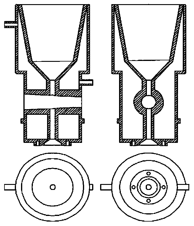
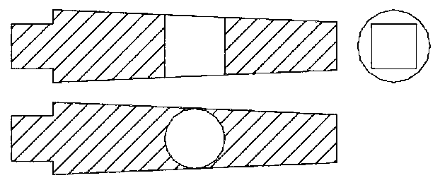
[0032] refer to Figure 1-9, The present inv...
PUM
 Abstract
Description
Claims
Application Information