Positioning clamp device with automatic cleaning function

An automatic cleaning and gripper technology, which is applied in the field of machine tools, can solve the problems affecting the sliding of the slider, the friction loss of the slider and the guide rail, etc., and achieve the effects of saving power resources, convenient operation and simple structure

Active Publication Date: 2019-08-30
CHONGQING HONGGANG CNC MACHINE TOOL
View PDF6 Cites 1 Cited by
  • Summary
  • Abstract
  • Description
  • Claims
  • Application Information

AI Technical Summary

Problems solved by technology

[0004] The present invention intends to provide a positioning gripper with automatic cleaning function to solve the problem in the prior art that foreign matter on the

Method used


Image

  • Positioning clamp device with automatic cleaning function
  • Positioning clamp device with automatic cleaning function

Examples


Example Embodiment

[0021] Example one

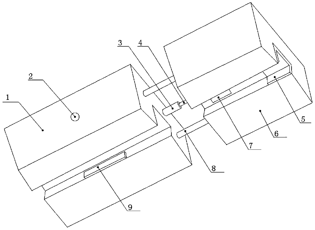
[0022] Such as figure 1 As shown, the positioning clamp with automatic cleaning function includes a clamping block, and the clamping block is slidably arranged on the inner wall of the slider 1 for connecting with the guide rail. The structure of slider 1 is figure 1 As shown, the bottom of the slider 1 is provided with a sliding groove that matches with the guide rail. Clamping blocks 9 are slidably connected to the inner walls on both sides of the slider 1. The two clamping blocks 9 are connected with a driving mechanism for driving their sliding movement. In this embodiment, the driving mechanism includes a main oil pipe 2 installed in the slider 1, and one end of the main oil pipe 2 extends out of the slider 1 to connect a hydraulic system. The clamping block 9 is slidably connected with the main oil pipe 2. Specifically, a piston can be sealed and slidingly connected in the main oil pipe 2, and then the clamping block 9 is connected with the piston, and...

Example Embodiment

[0032] Example two

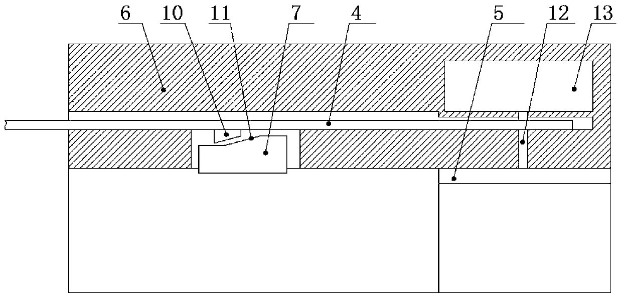
[0033] The difference between this embodiment and the first embodiment is that both ends of the slider 1 are provided with a cleaning mechanism. This arrangement requires reverse movement on the saddle. The cleaning mechanism at the other end of the slider 1 can be used to automatically clean the guide rail. . In addition, the sponge layer 5 in this embodiment can be detachably arranged. Specifically, a method in the prior art can be used, such as adhesive bonding, to realize the detachable arrangement of the sponge layer 5. This arrangement facilitates the replacement of the sponge layer 5.

[0034] The present invention cleans the guide rail by arranging a cleaning mechanism on both sides of the slider 1, which can prevent foreign matter on the guide rail from getting stuck between the slider 1 and the guide rail and affecting the movement of the slider 1, and at the same time avoid foreign matter from wearing the slider 1 and the guide rail. In addition, t...


PUM


Abstract

The invention relates to the technical field of machine tools, in particular to a positioning clamp device with an automatic cleaning function. A clamping block arranged on the inner wall of a slidingblock in a sliding manner is included, wherein the sliding block is used for being connected with a guide rail. The clamping block is connected with a drive mechanism for driving the clamping block to slide. The front end, in the motion direction, of the sliding block is provided with a cleaning block which is in sliding connection with the guide rail. The inner wall of the cleaning block is provided with a wiping piece for wiping the guide rail. The positioning clamp device solves the problems that in the prior art, foreign matter on a guide rail is clamped between a sliding block and the guide rail, sliding block sliding is influenced, and consequently the sliding block and guide rail friction losses are large.

Description

technical field [0001] The invention relates to the technical field of machine tools, in particular to a positioning holder with automatic cleaning function. Background technique [0002] In the prior art machine tools with an inclined bed layout, when in use, the saddle parts installed on the guide rails usually brake rapidly according to instructions due to processing technology requirements. In the prior art, the motor drives the saddle screw rod, and the braking of the saddle is realized by the motor. However, due to the machine tool with inclined bed layout, the saddle is easy to move downward due to inertia after braking, and the positioning is unstable, which is easy to affect the motor and lead screw, and cannot guarantee the machining accuracy requirements. [0003] In order to solve the above problems, a quick brake saddle has appeared in the prior art, which includes a slider slidingly connected to the guide rail of the machine tool, and a clamping block slidingl...

Claims


Application Information

Patent Timeline
IPC IPC(8): B23Q1/01B23Q1/70B23Q11/12B23Q11/00
CPCB23Q1/017B23Q1/70B23Q11/00B23Q11/124
Inventor 汪传宏
Owner CHONGQING HONGGANG CNC MACHINE TOOL
Why Eureka
Try Eureka