Cable core recovery device

A technology for recycling equipment and cable cores, which is applied in the field of cable core recycling equipment, can solve problems such as pollution, high labor intensity, and low efficiency, and achieve high metal recovery rate, convenient arrangement, and prevent excessive extension.

Active Publication Date: 2019-09-06
无锡市兆亨线缆有限公司
View PDF4 Cites 5 Cited by
  • Summary
  • Abstract
  • Description
  • Claims
  • Application Information

AI Technical Summary

Problems solved by technology

[0003] In order to overcome the disadvantages of low efficiency, high manual labor intensity and serious pollution of the existing method for separating the cable core and the wire sheath, the purpose of the present invention is to provide a cable core with high peeling efficiency, which can reduce the manual labor intensity and is more environmentally friendly. recycling equipment

Method used


Image

  • Cable core recovery device
  • Cable core recovery device
  • Cable core recovery device

Examples


Embodiment 1

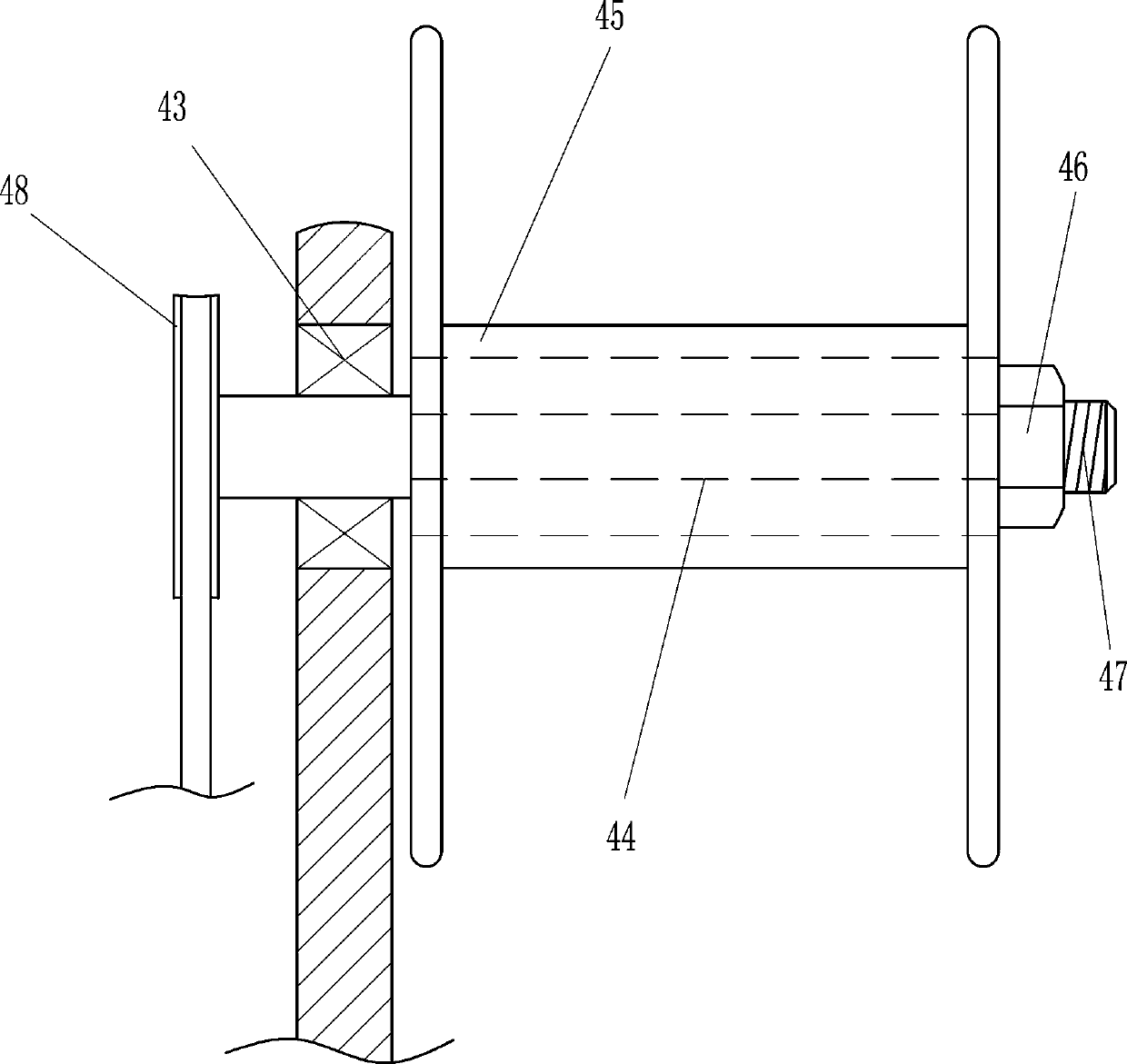
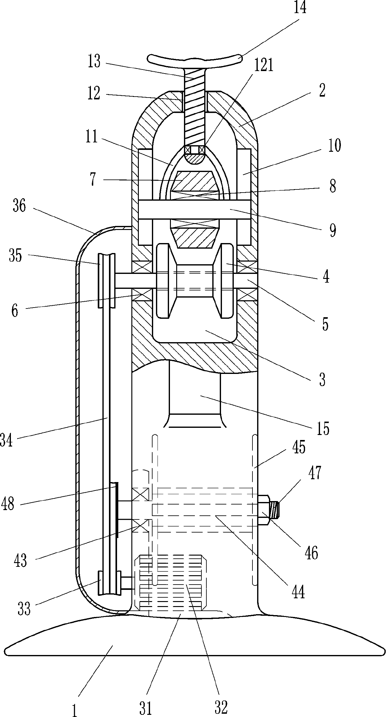
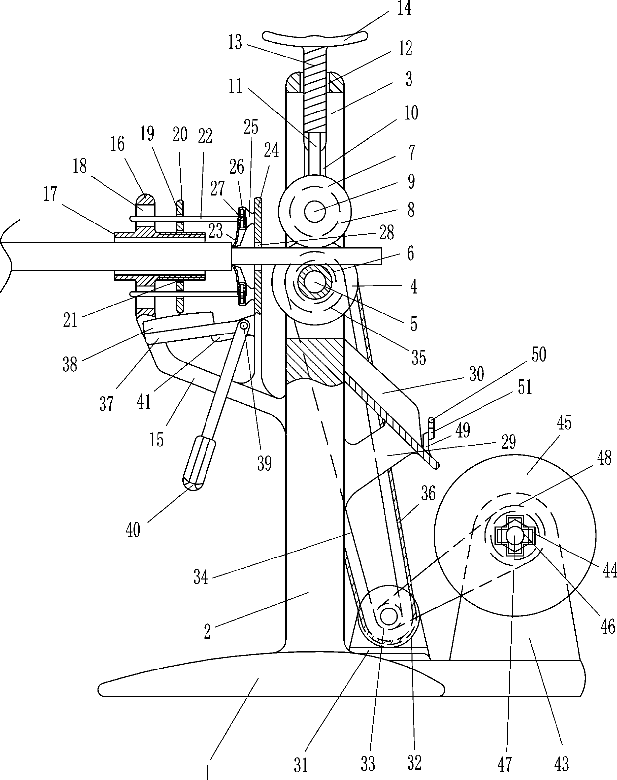
[0021] A cable core recovery device, such as Figure 1-5As shown, it includes a base 1, a bracket 2, a groove runner 4, a rotating shaft 5, a first bearing 6, a nose runner 7, a second bearing 8, a first mandrel 9, a first connecting rod 11, a first One bolt 13, rotary handle 14, pole 15, fixed frame 16, cylindrical hollow pipe 17, rotating disc 19, circular rod 22, cutter 23, baffle plate 24, the first connecting block 25, grooved fixed block 26, slide Block 27, the second connection block 29, funnel 30, motor mounting plate 31, rotating motor 32, double groove pulley 33, V-belt 34, first single groove pulley 35 and protective shell 36, base 1 top is connected with support 2, support 2 The upper part is provided with a first through hole 3, and the upper part of the front and rear sides of the bracket 2 is embedded with a first bearing 6, and the first bearing 6 on the front and rear sides is interference-connected with a rotating shaft 5, and the middle part of the rotating ...

Embodiment 2

[0023] A cable core recovery device, such as Figure 1-5 As shown, it includes a base 1, a bracket 2, a groove runner 4, a rotating shaft 5, a first bearing 6, a nose runner 7, a second bearing 8, a first mandrel 9, a first connecting rod 11, a first One bolt 13, rotary handle 14, pole 15, fixed frame 16, cylindrical hollow pipe 17, rotating disc 19, circular rod 22, cutter 23, baffle plate 24, the first connecting block 25, grooved fixed block 26, slide Block 27, the second connection block 29, funnel 30, motor mounting plate 31, rotating motor 32, double groove pulley 33, V-belt 34, first single groove pulley 35 and protective shell 36, base 1 top is connected with support 2, support 2 The upper part is provided with a first through hole 3, and the upper part of the front and rear sides of the bracket 2 is embedded with a first bearing 6, and the first bearing 6 on the front and rear sides is interference-connected with a rotating shaft 5, and the middle part of the rotating...

Embodiment 3

[0026] A cable core recovery device, such as Figure 1-5 As shown, it includes a base 1, a bracket 2, a groove runner 4, a rotating shaft 5, a first bearing 6, a nose runner 7, a second bearing 8, a first mandrel 9, a first connecting rod 11, a first One bolt 13, rotary handle 14, pole 15, fixed frame 16, cylindrical hollow pipe 17, rotating disc 19, circular rod 22, cutter 23, baffle plate 24, the first connecting block 25, grooved fixed block 26, slide Block 27, the second connection block 29, funnel 30, motor mounting plate 31, rotating motor 32, double groove pulley 33, V-belt 34, first single groove pulley 35 and protective shell 36, base 1 top is connected with support 2, support 2 The upper part is provided with a first through hole 3, and the upper part of the front and rear sides of the bracket 2 is embedded with a first bearing 6, and the first bearing 6 on the front and rear sides is interference-connected with a rotating shaft 5, and the middle part of the rotating...


PUM


Abstract

The invention relates to a recovery device, in particular to a cable core recovery device. The invention aims to provide the cable core recovery device which is high in stripping efficiency, low in labor intensity and relatively environment-friendly. According to the technical scheme, the cable core recovery device comprises a base, a bracket, a groove rotating wheel, a rotating shaft, first bearings, a convex head rotating wheel, a second bearing, a first mandrel, a first connecting rod, a first bolt, a rotating handle and the like; the top of the base is connected with the bracket; the upperpart of the bracket is provided with a first through hole; and the upper parts of the front side and the rear side of the bracket are embedded with the first bearings. According to the cable core recovery device, an operator penetrates a cable between cutters on the upper and lower sides, and a rotary motor is started to rotate clockwise, so that the cutters can well cut cable sheath; the cable core recovery device is high in stripping efficiency, low in labor intensity and relatively environment-friendly; the damage to a cable core can be prevented; and relatively high metal recovery rate can be ensured.

Description

technical field [0001] The invention relates to a recycling device, in particular to a cable core recycling device. Background technique [0002] If waste cables are discarded directly, it will cause serious harm to the environment. Therefore, the society now advocates the recycling of waste cables, which can not only reduce costs, meet the needs of other occasions, but also meet environmental protection requirements. The purpose of cable recycling is to reuse the metal. Generally, only the wire core can be processed. The wire sheath has lost its use, so the wire core and the sheath must be separated. There are two kinds of existing separation methods. One is the manual peeling method. The cable is cut manually with a wire stripper or a knife, and then the wire skin is torn off. This method has low efficiency and high cost, and the manual operation environment is relatively Poor, labor-intensive, prone to injury accidents. Another method is the incineration method, which b...

Claims


Application Information

Patent Timeline
Patent Type & Authority Applications(China)
IPC IPC(8): H01B15/00
CPCH01B15/006Y02W30/82
Inventor 叶春明
Owner 无锡市兆亨线缆有限公司
Why Eureka
Try Eureka