Vision correcting device for presbyopia

A vision correction and presbyopia technology, applied in the field of optics, can solve the problems of not ideal optical system, large lens thickness, and inability to see the scene clearly, and achieve the effect of wide vision adjustment range

Active Publication Date: 2019-09-27
SHENZHEN LUBANG TECH CO LTD
View PDF4 Cites 4 Cited by
  • Summary
  • Abstract
  • Description
  • Claims
  • Application Information

AI Technical Summary

Problems solved by technology

Existing technical solutions for vision correction generally use traditional curved concave / convex lenses to realize the divergence / focus of light beams. The disadvantages are: 1. The lens is thick and heavy, especially for high myopia above 1000 degrees. It reaches about 10mm; 2. The curved lens is not an ideal optical system, and it cannot form a perfect image, and there will inevitably be aberrations, which make the scene perceived by the human eye deviate from the reality
In reality, there are also patients with double vision defects who suffer from both myopia and presbyopia, and cannot see distant and near scenes clearly
If equipped with two sets of glasses for myopia and hyperopia, it is very inconvenient to carry and switch back and forth; ordinary positive and negative bifocal glasses integrating hyperopia and myopia correction functions have serious visual field defects, and the present invention aims to solve the above problems

Method used


Image

  • Vision correcting device for presbyopia
  • Vision correcting device for presbyopia
  • Vision correcting device for presbyopia

Examples


Embodiment 1

[0026] This embodiment discloses a vision correction device for presbyopia, comprising: a linear polarizer, a first flat lens based on an electrically controlled birefringence material, and a 1 / 4 wave plate between the linear polarizer and the first flat lens, and Voltage control system for switching flat lens. Optionally, the birefringent material in this embodiment is made of liquid crystal or liquid crystal polymer.

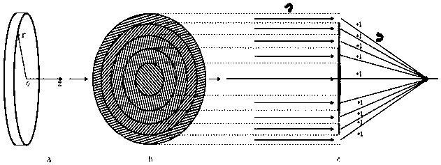
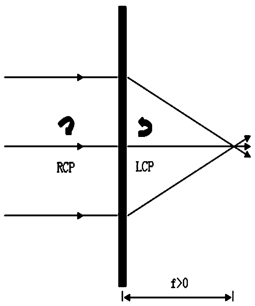
[0027] In this embodiment, the voltage control system is specifically used to control the switch state of the first flat lens, so that: in the case of no electric field when the circuit of the corresponding voltage control system is disconnected, the first flat lens, as figure 1 As shown, achieving a non-zero diffracted beam of the same order is equivalent to converging the beam with a real focal point by a convex lens. On the other hand, if the first flat lens is in the saturated electric field corresponding to the closed circuit of the voltage control syste...

Embodiment 2

[0048] In this embodiment, on the basis of the first embodiment above, the following product improvements are made for users who have presbyopia and myopia at the same time. The specific improvement includes: adding a second flat lens adjacent to the first flat lens in the above device, and the rotation directions of the fast axes of the second flat lens and the first flat lens are opposite to each other under the condition of no electric field.

[0049] In this way, when the first flat lens and the second flat lens are replaced under the condition of no electric field, when the incident light of the same polarization state converges after passing through the first flat lens, the incident light of the polarization state passes through the second flat plate After the lens diverges, or when incident light of the same polarization state diverges after passing through the first flat lens, the incident light of the same polarization state converges after passing through the second f...

Embodiment 3

[0056] Further, on the basis of the first and second embodiments above, this embodiment makes intelligent improvements based on user experience. It specifically includes: setting a working mode sensor in the voltage control system to detect whether the user's head is a bowing action for observing a close-up view, or a head-up or looking-up action based on a distant view; Adaptive electric field state switching. Optionally, the working mode sensor includes but is not limited to a level sensor or other sensors based on visual changes of the user's eyes.

[0057] Optionally, the voltage control system in this embodiment is also provided with a matching switch for the user to enable or disable the adaptive electric field switching based on the working mode sensor. Usually, this switch can not only turn off the automatic switching function to avoid misjudgment, but also allow us to manually switch between the first and second flat lens. In other words, the matching switch can be ...


PUM


Abstract

The invention relates to the technical field of optics, and discloses a vision correcting device for presbyopia in order to optimize the user experience and realize convenience and light weight. The device comprises a linear polarizer, a first slab lens based on an electrically controlled birefringence material, a quarter-wave plate between the linear polarizer and the first slab lens, and a voltage control system used for switching the slab lens in order to enable the first slab lens to realize nonzero diffraction light beams at the same stage to be equivalent to a convex lens to focus the light beam at a real focus in a free electric field corresponding to circuit opening of the voltage control system, and to realize a function of being equivalent to a slab window sheet in a saturated electric field corresponding to circuit closing of the voltage control system.

Description

technical field [0001] The invention relates to the field of optical technology, in particular to a vision correction device for presbyopia. Background technique [0002] The core principle of the vision correction device is to diverge or focus the ambient light incident on the human eye to a certain extent through the optical system, so that the imaging beam can finally focus on the retina of the human eye. Existing technical solutions for vision correction generally use traditional curved concave / convex lenses to realize the divergence / focus of light beams. The disadvantages are: 1. The lens is thick and heavy, especially for high myopia above 1000 degrees. It reaches about 10mm; 2. The curved lens is not an ideal optical system, and it cannot form a perfect image. There must be aberrations, which makes the scene perceived by the human eye deviate from the reality. [0003] It is worth explaining that presbyopia, like hyperopia, cannot see things close up clearly, and nee...

Claims


Application Information

Patent Timeline
Patent Type & Authority Applications(China)
IPC IPC(8): G02C7/08G02C7/10G02C7/12
CPCG02C7/08G02C7/101G02C7/12
Inventor 陈琪张礼朝李晓春
Owner SHENZHEN LUBANG TECH CO LTD
Why Eureka
Try Eureka