Multi-station lathe

A multi-station, lathe technology, applied in the field of lathes, can solve the problems of machine tools occupying a lot of space, wasting manpower and material resources, and wasting resources, and achieve the effects of saving resources, saving time, saving resources and space

Pending Publication Date: 2019-10-01
上海非圆科技有限公司
View PDF0 Cites 2 Cited by
  • Summary
  • Abstract
  • Description
  • Claims
  • Application Information

AI Technical Summary

Problems solved by technology

[0002] Existing lathes use one lathe head and multiple tools for processing, that is, only one workpiece can be processed at a time. According to different processes of the product, multiple tools are processed in turn on the slide table. The disadvantage is that any tool is processed separately. Several of the knives are in a waiting state, wasting a lot of time
[0003] When the existing lathe needs to process a workpiece with multiple processes, when one lathe cannot complete multiple processes, it is necessary to remove the semi-finished workpiece processed by the previous lathe and install it on another lathe for processing. During the process, the secondary clamping of the workpiece affects the accuracy of the workpiece
[0004] When the existing lathes process workpieces with multiple processes, if one lathe cannot complete the processing, multiple machine tools need to be connected to process, and the workpiece turnover between lathes needs to be removed from one lathe by hand or manipulator. Another machine tool, a lot of manpower and material resources were wasted in the process
[0005] If the existing lathes want to process a multi-process workpiece, multiple lathes are required to cooperate with each other. If there are more machine tools, it will take up more space, waste more resources, and management will be troublesome.

Method used


Image

  • Multi-station lathe
  • Multi-station lathe
  • Multi-station lathe

Examples


Embodiment Construction

[0025] The following descriptions are only preferred embodiments of the present invention, and do not limit the protection scope of the present invention. The present invention will be further described below in conjunction with the accompanying drawings and embodiments.

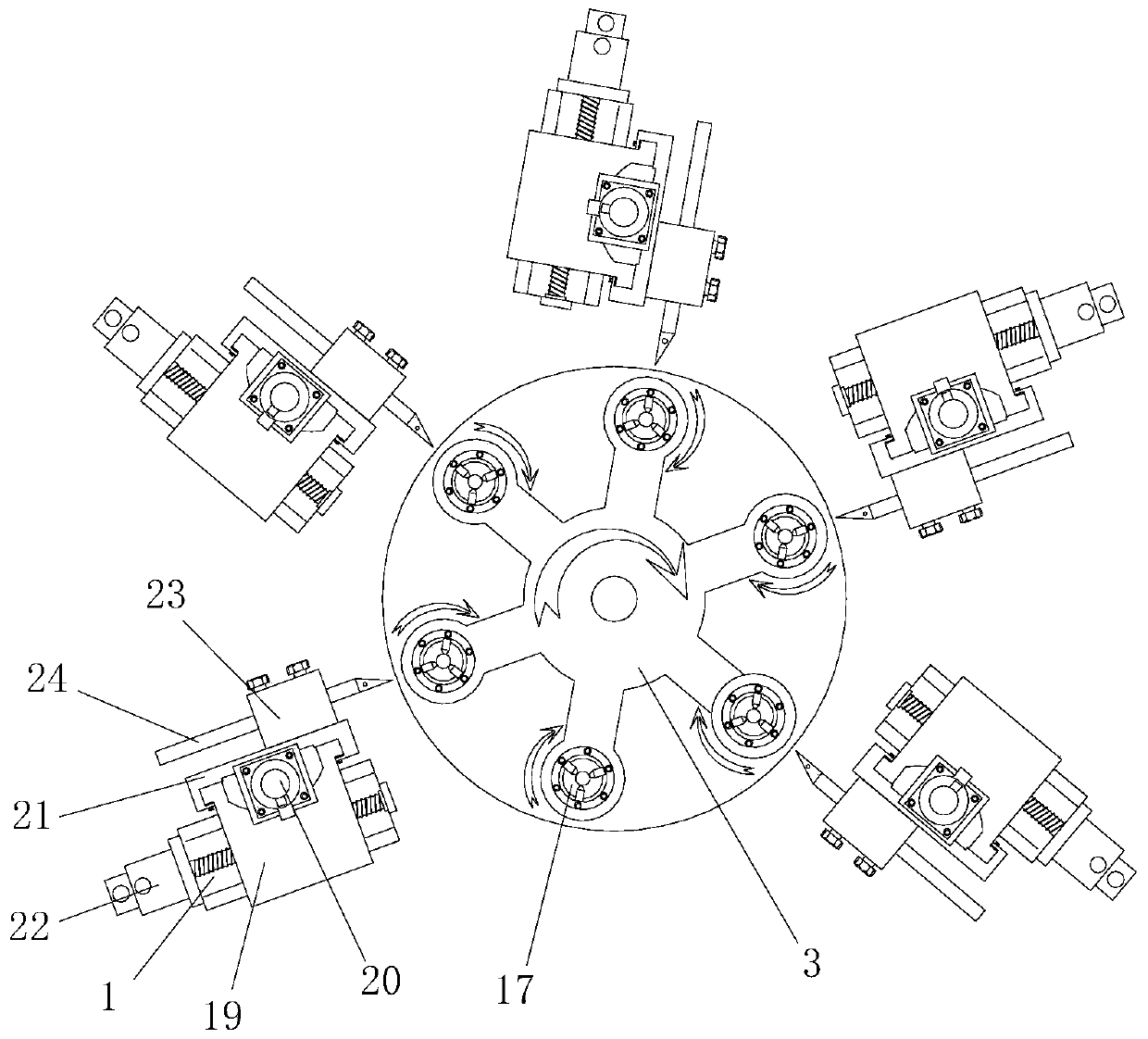
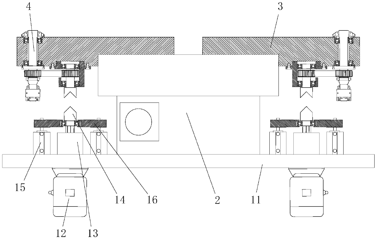
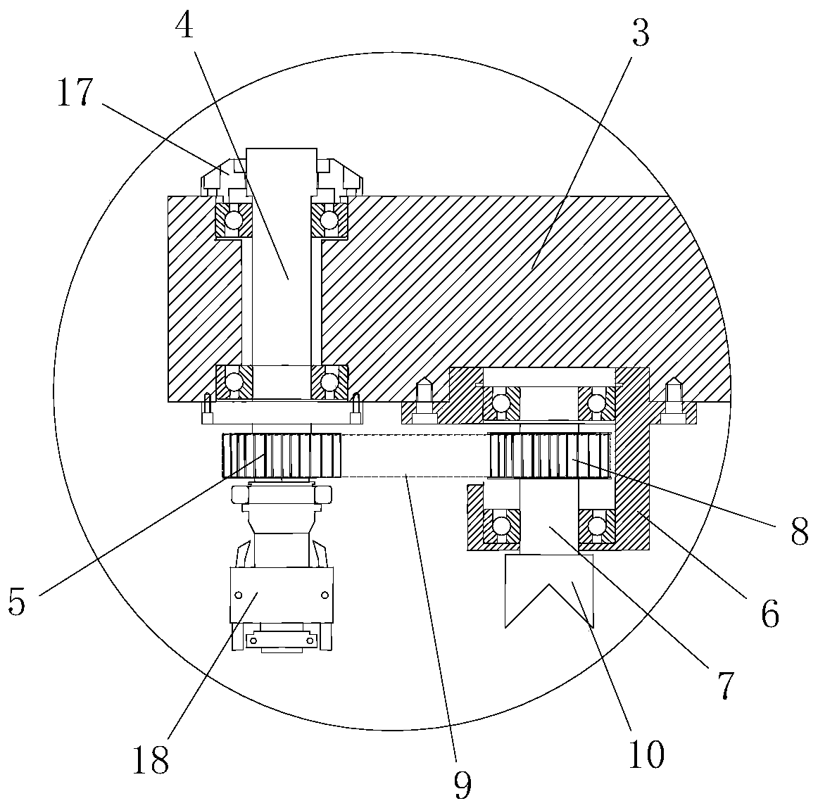
[0026] Examples, see Figure 1 to Figure 3 Shown: a multi-station lathe, including a lathe body, a numerically controlled index plate installed on the lathe body, and a tool holder 1. The numerically controlled index plate includes a main disc body 2 and is connected with the main disc body 2 The rotating disk body 3; also includes a plurality of independently rotatable lathe spindles 4 evenly arranged along the circumference of the rotating disk body 3, and the lathe spindles 4 are set to 2, 3, 4, 5 , 6, 7 or 8, the present embodiment takes 6 as an example; the lathe spindle 4 is provided with a clamping device for clamping the workpiece.

[0027] specific,

[0028] Numerical control indexing plate, the n...


PUM


Abstract

The invention discloses a multi-station lathe. The lathe comprises a lathe main body and a dividing plate installed on the lathe main body, the dividing plate comprises a main disc body and a rotatingdisc body which is connected with the main disc body in a matched mode, the lathe is characterized by further comprising a plurality of independently-rotatable lathe spindles uniformly distributed along the circumferential direction of the rotary disc body, clamping devices used for clamping workpieces is arranged on the lathe spindles. The multi-station lathe has the advantages that a pluralityof cutters correspond to a plurality of different working procedures respectively, a plurality of cutters can simultaneously process a plurality of workpieces at the same time, and the workpiece machining efficiency is improved; a plurality of cutters are used for simultaneously processing a plurality of workpieces at the same time, then the rotary disc body is rotated to enable each workpiece toenter the next working procedure for further processing, so that the workpiece with multiple procedures can be completed on one lathe bed; the workpiece turnover between the lathe and the lathe is avoided, so that a lot of manpower and material resources are saved; a plurality of working procedures do not need to be carried out on a workpiece and a plurality of lathes do not need to be placed, resources and space are saved, and management is facilitated.

Description

technical field [0001] The invention belongs to the technical field of lathes, in particular to a multi-station lathe. Background technique [0002] Existing lathes use one lathe head and multiple tools for processing, that is, only one workpiece can be processed at a time. According to different processes of the product, multiple tools are processed in turn on the slide table. The disadvantage is that any tool is processed separately. Several knives are in a waiting state, wasting a lot of time. [0003] When the existing lathe needs to process a workpiece with multiple processes, when one lathe cannot complete multiple processes, it is necessary to remove the semi-finished workpiece processed by the previous lathe and install it on another lathe for processing. During the process, the secondary clamping of the workpiece affects the accuracy of the workpiece. [0004] When the existing lathes process workpieces with multiple processes, if one lathe cannot complete the pro...

Claims


Application Information

Patent Timeline
Patent Type & Authority Applications(China)
IPC IPC(8): B23B3/30B23Q1/25B23Q3/00B23Q3/06
CPCB23B3/30B23Q1/25B23Q3/00B23Q3/06
Inventor 吴思雄
Owner 上海非圆科技有限公司
Why Eureka
Try Eureka