

Current collector of capacity type battery
A current collector and battery technology, applied in battery pack parts, electrode carriers/current collectors, circuits, etc., can solve the problems of reducing batteries, difficulty in upper current, and destruction of positive particles, and achieves increase in output capacity and internal resistance increase. Small, consistent effect
- Summary
- Abstract
- Description
- Claims
- Application Information
AI Technical Summary
Problems solved by technology
Method used
Image

Examples
Embodiment Construction
[0028] The present invention will be further described in detail below in conjunction with the accompanying drawings and specific embodiments.
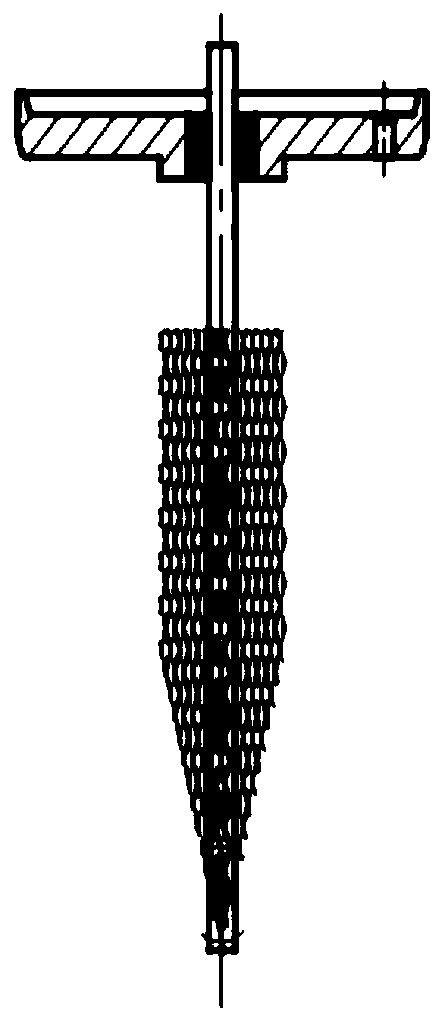
[0029] figure 1 It is a schematic diagram of the current collector structure in the prior art, which has been introduced in detail in the background art, and will not be repeated here.
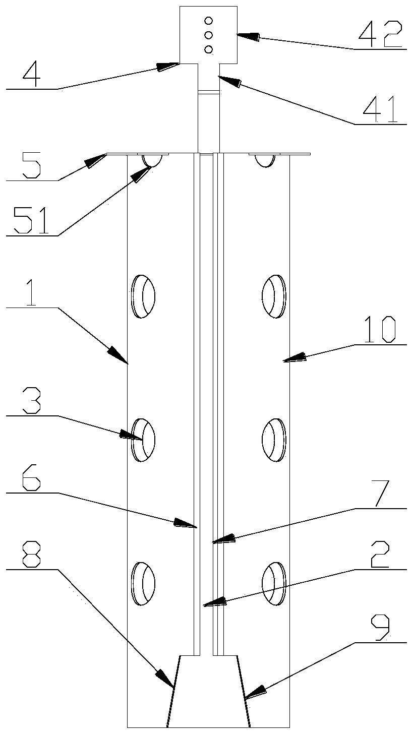
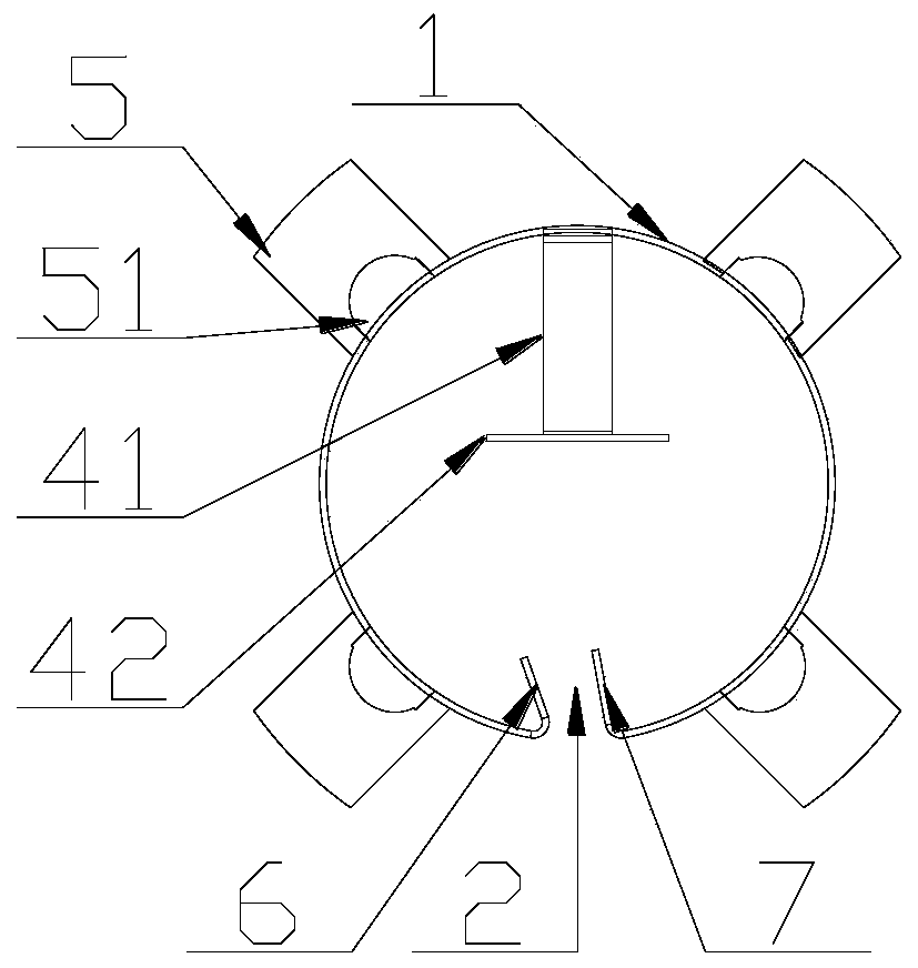
[0030] like Figure 2-4 As shown, the present invention provides a current collector for a capacity-type battery. The current collector 10 includes a cylindrical main body 1. The main body 1 is provided with an axially penetrating opening 2. The main body 1 is provided with a plurality of through holes 3 and the main body The upper end of 1 extends axially to form a tab 4 . The upper end of the main body 1 extends axially to form a positioning piece 5 , a plurality of positioning pieces 5 are arranged at intervals in the circumferential direction, and a process hole 51 is provided at the connection between each positioning piece 5 and the main body ...
PUM
 Abstract
Description
Claims
Application Information