
A magnetic self-switching infrared monitor
A self-switching and monitoring technology, applied in CCTV systems and other directions, can solve the problems of insufficient light, poor shooting effect, fixed infrared switching time, etc., to achieve strong flexibility, reduce impact, and improve shooting clarity.
- Summary
- Abstract
- Description
- Claims
- Application Information
AI Technical Summary
Problems solved by technology
Method used
Image

Examples
Embodiment 1
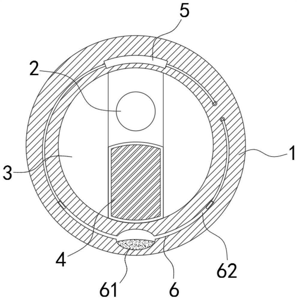
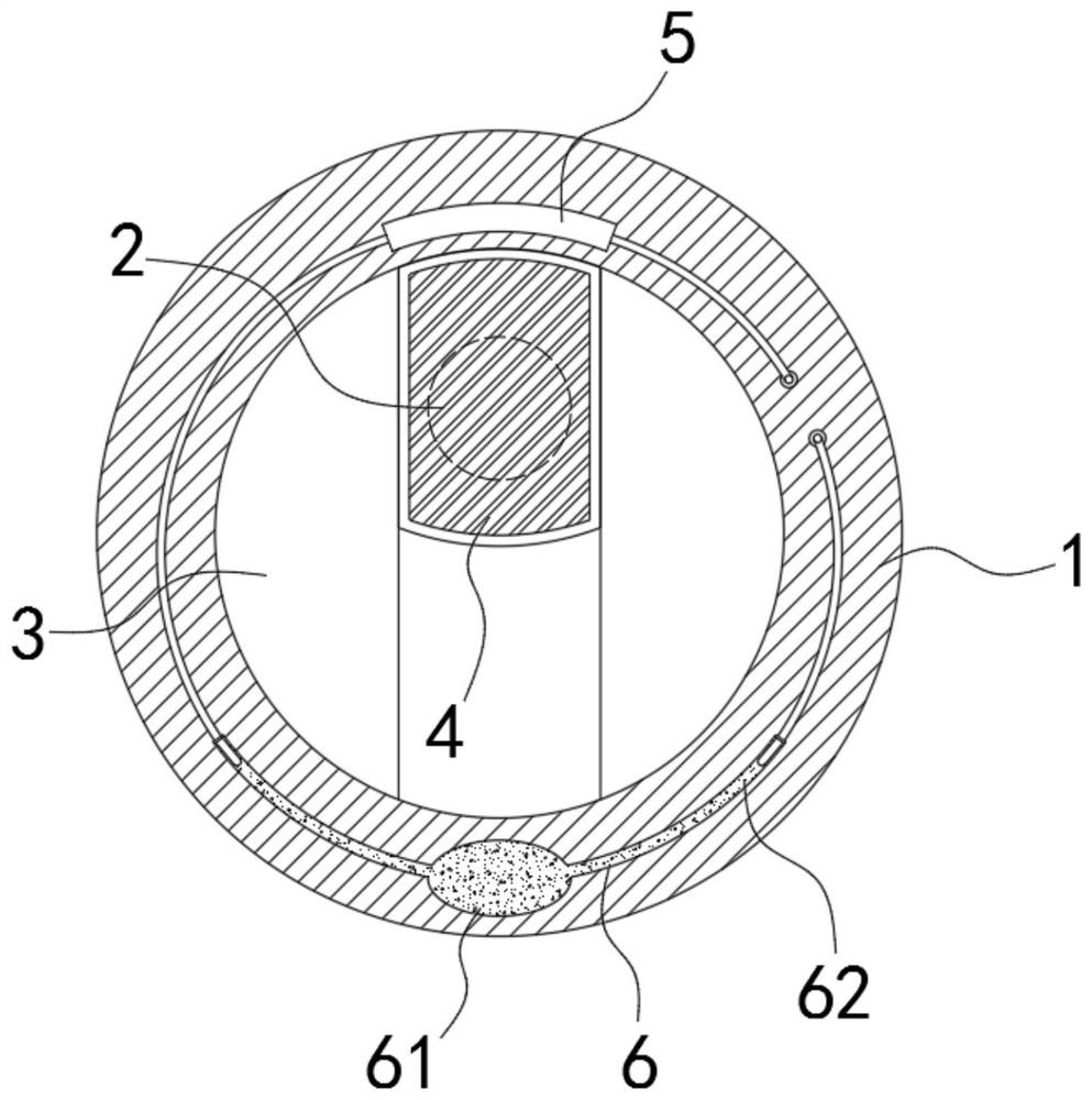
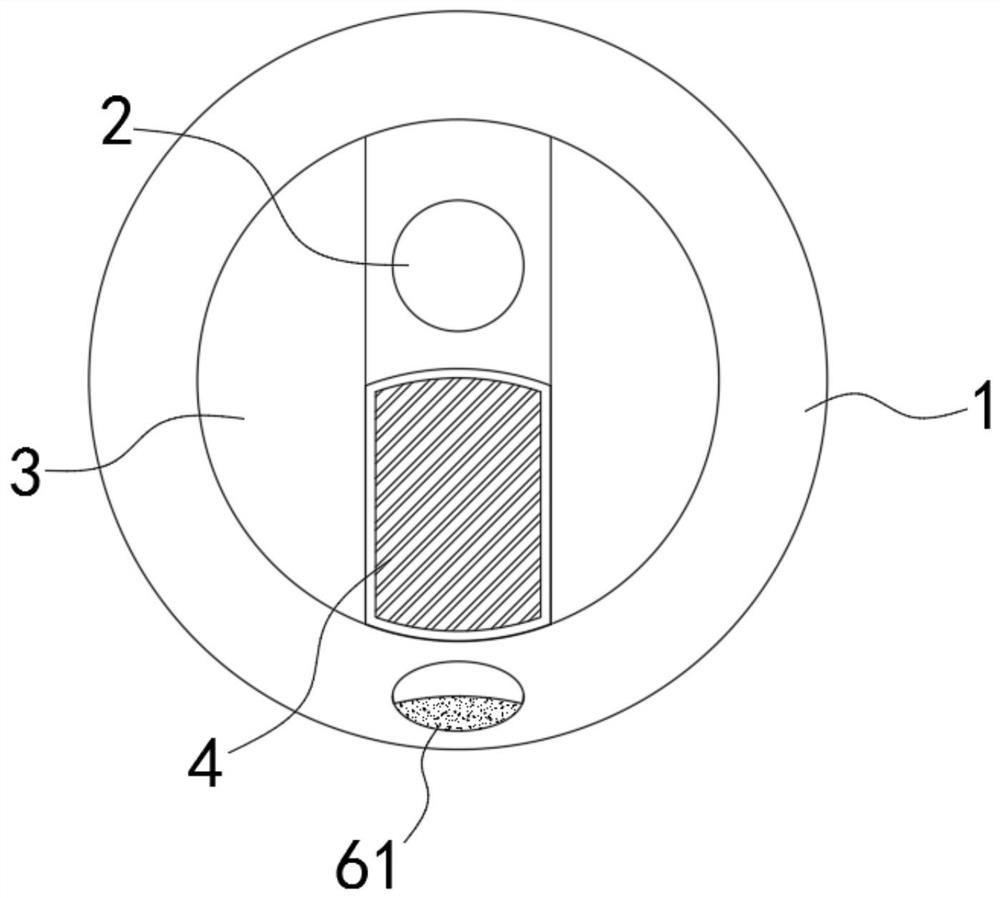
[0020] Such as Figure 1-3 As shown, a magnetic self-switching infrared monitor includes a cylindrical housing 1, and a monitoring head 2 is installed on the upper half of the housing 1, that is, the monitoring head 2 is arranged on the axis of the cylindrical housing 1 In the above part, both sides of the monitoring head 2 are provided with arc-shaped blocks 3, a vertical slideway is formed between the two arc-shaped blocks 3, and the infrared cut-off plate 4 is slidably connected in the slideway, and the frame of the infrared cut-off plate 4 Using magnetic material, under the initial state, under the action of gravity of the infrared cut-off plate 4, the infrared cut-off plate 4 is at the lowermost side of the slideway (such as figure 1 As shown), at this time, the monitoring head 2 is directly exposed to the outside, which can meet the requirement that the monitoring head 2 has enough light at night or on cloudy days. The upper part of the housing 1 is embedded with an elec...
Embodiment 2
[0024] Such as Figure 4 As shown, the difference between this embodiment and Embodiment 1 is that the temperature control switch 6 includes a slot arranged on the upper part of the housing 1, and a transparent block 63 is fixedly connected in the slot, and the edge of the transparent block 63 is in contact with the housing 1. The outer edge of the transparent block 63 is matched to form a complete cylinder. The cross-section of the transparent block 63 is in the shape of a shuttle with two sides facing outwards with arc-shaped protrusions and two pointed ends. An upwardly curved, arc-shaped, A flat vacuum chamber 64 containing mercury, and conductive contacts embedded in the upper end surfaces of both sides of the vacuum chamber 64 .
[0025] In this embodiment, when external strong light passes through the transparent block 63 and irradiates the mercury to increase its temperature, the mercury expands when heated and will cover the vacuum chamber 64 and form a concave mirror...
PUM
 Abstract
Description
Claims
Application Information