
Metal structure health detection method based on UHF passive RFID
A metal structure and health detection technology, which is applied in the direction of cooperative devices, special data processing applications, instruments, etc., can solve problems such as inability to detect metal features, and achieve comprehensive effects
- Summary
- Abstract
- Description
- Claims
- Application Information
AI Technical Summary
Problems solved by technology
Method used
Image

Examples
Embodiment
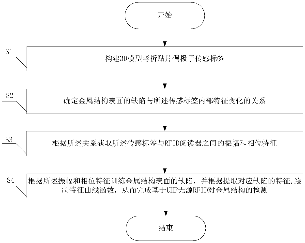
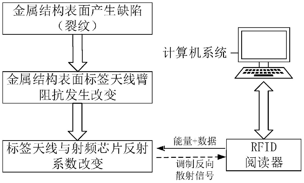
[0047] Such as figure 1 As shown, the present invention provides a metal structure health detection method based on UHF passive RFID, and its specific implementation block diagram is as follows figure 2 shown. According to the present invention, defects (cracks) appear on the metal surface in the exposed environment or under huge pressure, which indirectly causes the impedance of the antenna arm to change. According to this characteristic change, the RFID technology can be used to realize real-time detection of the health of the metal structure. The specific implementation steps are as follows:
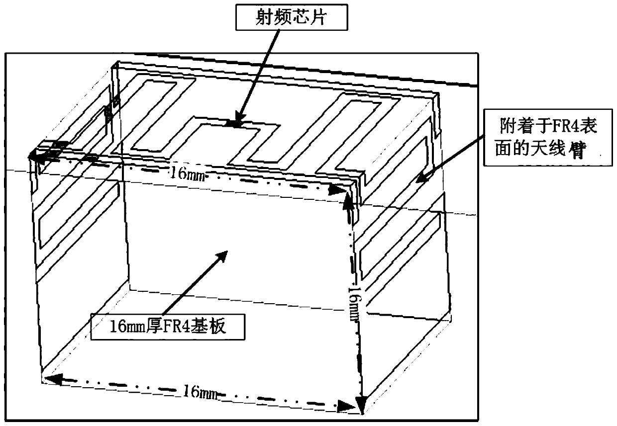
[0048] S1. Build a 3D model to bend the patch dipole sensor tag, such as image 3 As shown, the sensing tag in step S1 includes a 16mm thick FR4 substrate, an antenna arm attached to the surface of the FR4 substrate, and a radio frequency chip connected to the antenna arm.
[0049] In this embodiment, for the design of the 3D model miniaturized bent patch dipole sensor tag in step...
PUM
 Abstract
Description
Claims
Application Information