Voltage source inverter control method applied to grid connection mode of micro-grid system

A technology of voltage source inverters and micro-grids, applied in electrical components, circuit devices, AC network circuits, etc., can solve problems such as poor stability of the control system, achieve a balance between dynamic performance and stability, and improve stability

Active Publication Date: 2019-12-31
SOLAR POWER NETWORK TECHNOLOGY (ZHEJIANG) CO LTD
View PDF1 Cites 1 Cited by
  • Summary
  • Abstract
  • Description
  • Claims
  • Application Information

AI Technical Summary

Problems solved by technology

[0020] (2) When the active power P o and reference output active power P ref When the deviation of is not equal to 0, the droop coefficient m ω The larger the value, the smaller the deviation between the two, but m ω The larger the , the worse the stability of the control system, so m ω The value of needs to be compromised;
[0021] (3) The angular frequency ω of the public grid voltage g is changing in real time, but the rated angular frequency ω of the inverter output voltage r and the sag coefficient m ω is fixed, so the active power P o The deviation from the reference output active power will also change in real time, that is, the active power P o The control accuracy will be affected by the change of grid voltage frequency
[0022] 2. The traditional droop method grid-connected control strategy cannot achieve precise control of the output reactive power Q o , reactive power Q o and reference output reactive power Q ref The deviation of can be given by the formula Indicates that where V ref means when Q o equal to Q ref When is the theoretical effective value of the inverter output voltage, E represents the effective value of the grid voltage
[0025] (2) When the reactive power Q o and reference output reactive power Q ref When the deviation is not equal to 0, the droop coefficient n v The larger the value, the smaller the deviation between the two, but the droop coefficient n v The larger is, the worse the stability of the control system is, so the droop coefficient n v The value of needs to be compromised;
[0028] (5) The effective value E of the public grid voltage changes in real time, but the rated effective value V of the inverter output voltage r and the droop coefficient n v is fixed, so the reactive power Q o and reference output reactive power Q ref The deviation of will also change in real time, that is, the reactive power Q o The control accuracy will be affected by the change of grid voltage frequency
[0029] From the above, it can be seen that the traditional droop method grid-connected control strategy cannot be based on the reference active power P ref and reactive power Q ref Accurately control the output active power P of the inverter o and reactive power Q o

Method used


Image

  • Voltage source inverter control method applied to grid connection mode of micro-grid system
  • Voltage source inverter control method applied to grid connection mode of micro-grid system

Examples


Embodiment Construction

[0047] The technical solutions of the present invention will be further described below in conjunction with the accompanying drawings, but the present invention is not limited to these embodiments.

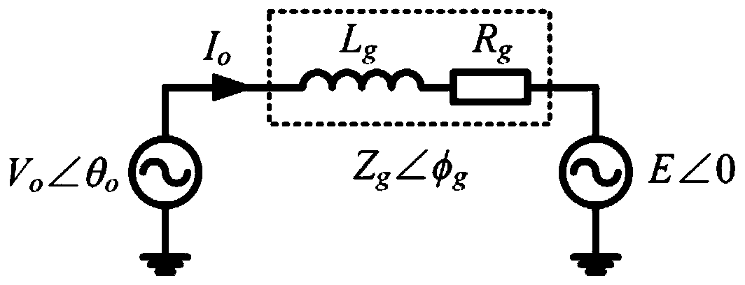
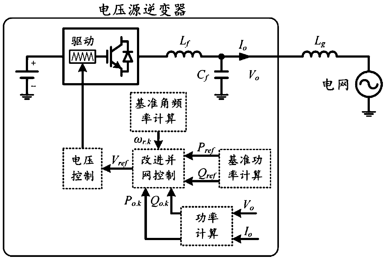
[0048] A voltage source inverter control method applied to the grid-connected mode of a micro-grid system, the micro-grid system comprising: several power generation units, each power generation unit adopts a voltage source inverter and is connected to the public power grid through a fixed connection impedance , the method includes:

[0049] In the kth control period, according to the formula ω r.k = ω r.k-1 -m p (P o.k-1 -P ref ) to calculate the reference angular frequency ω of the kth control cycle r.k , according to the formula Calculate the angular frequency ω of the output voltage in the kth control cycle o.k and rms V o.k , and according to the angular frequency ω o.k and rms V o.k Calculate the reference voltage V of the inverter ref , and then according to the...


PUM


Abstract

The invention relates to the field of micro-grids, and in particular relates to a voltage source inverter control method applied to the grid connection mode of a micro-grid system. The micro-grid system comprises a number of power generating units. Each power generating unit uses a voltage source inverter, and is connected with a public grid through a fixed connection impedance. The method comprises the steps that the reference angular frequency omega r.k of the k-th control period is calculated during the k-th control period; the angular frequency omega o.k and the effective value Vo.k of theoutput voltage in the k-th control period are calculated; according to the angular frequency omega o.k and the effective value Vo.k, the reference voltage Vref of an inverter is calculated; the output voltage of the voltage source inverter is controlled according to the reference voltage Vref, so as to control the output active power Po and reactive power Qo of the voltage source inverter; and the output active power Po of the voltage source inverter is equal to the active power Pref of the reference output of the voltage source inverter, and the output reactive power Qo of the voltage sourceinverter is equal to the reactive power Qref of the reference output of the voltage source inverter.

Description

technical field [0001] The invention relates to the field of micro-grids, in particular to a voltage source inverter control method applied to a grid-connected mode of a micro-grid system. Background technique [0002] As the prices of fossil fuels such as oil and coal continue to rise, countries around the world are taking various measures to deal with the challenges brought about by the energy crisis. At present, the whole world is actively promoting the construction of new high-efficiency energy systems, among which distributed generation, renewable energy and micro-grid technology are one of the current research hotspots. [0003] Distributed power generation technology can integrate various types of renewable energy such as solar energy and wind energy and various energy storage units, and connect them to the common bus through power electronic devices such as inverters to form a micro-grid system to achieve high-efficiency energy utilization , and provide high-quality...

Claims


Application Information

Patent Timeline
IPC IPC(8): H02J3/38
CPCH02J3/381
Inventor 高明智刘超厚郭华为祝东敏
Owner SOLAR POWER NETWORK TECHNOLOGY (ZHEJIANG) CO LTD
Why Eureka
Try Eureka