Photovoltaic shutter

A blinds and photovoltaic technology, applied in the field of blinds, can solve the problems of air not being able to circulate with the outdoors, increase of harmful gases, depressing psychological burden, etc., achieve high photoelectric conversion efficiency, avoid the increase of harmful gases, and reduce the effect of psychological burden

Inactive Publication Date: 2020-01-31
CHANGSHU FRIENDS CONNECTOR TECH
View PDF8 Cites 0 Cited by
  • Summary
  • Abstract
  • Description
  • Claims
  • Application Information

AI Technical Summary

Problems solved by technology

[0002] Blinds are a style of windows, mainly used to block sunlight and protect privacy. The windows are opened and closed by rotating the window blades. At present, photovoltaic cells are installed on the blinds, which can convert the light energy blocked by the blinds into electrical energy for indoor use. People use it to share electricity consumption; converting sunlight into electrical energy will lead to poor indoor lighting; the patent (publication number CN101401216A) discloses a lighting shutter assembly, which converts sunlight into electrical energy through photovoltaic cells, and then uses the collected electrical energy Light the interior
[0003] The above patents make up for the shortcomings of poor indoor lighting, but the collection of sunlight by the shutters will cause the room to be in a dark and closed state for a long time, which is easy to cause a depressive psychological burden, and the shutters are closed or half closed in order to collect sunlight. The air in the room cannot communicate with the outside, and harmful gases such as carbon dioxide in the room increase, which makes people feel uncomfortable. Therefore, it is a technical problem to be solved by those skilled in the art to develop a shutter that can improve the indoor closed environment.

Method used


Image

  • Photovoltaic shutter
  • Photovoltaic shutter
  • Photovoltaic shutter

Examples


Embodiment Construction

[0026] The following will clearly and completely describe the technical solutions in the embodiments of the present invention with reference to the accompanying drawings in the embodiments of the present invention. Obviously, the described embodiments are only some, not all, embodiments of the present invention. Based on the embodiments of the present invention, all other embodiments obtained by persons of ordinary skill in the art without creative efforts fall within the protection scope of the present invention.

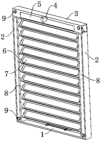
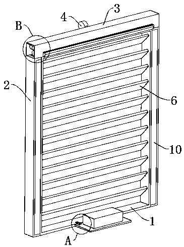
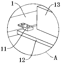
[0027] see Figure 1-7 , the present invention provides a technical solution: a photovoltaic shutter, including a main frame 1, side shells 2 are fixedly connected to both sides of the main frame 1, a top shell 3 is fixedly connected to the top of the main frame 1, and the front side wall of the top shell 3 is fixed Connected with a fixed rod 26, one end of the fixed rod 26 is fixedly connected with the detection box 4, eleven connecting shafts 25 run through both ...


PUM


Abstract

The invention discloses a photovoltaic shutter, and relates to the technical field of a shutter. The photovoltaic shutter comprises a main framework, wherein side cases are fixedly connected with twosides of the main framework; a top case is fixedly connected with the top of the main framework; the front side wall of the top case is fixedly connected with a fixing rod; one end of the fixing rod is fixedly connected with a detecting box; eleven connecting shafts penetrate through each of two sides of the inner walls of the main framework; one opposite ends of the two connecting shafts are fixedly connected with a rotating blade; the side wall of each rotating blade is fixedly connected with a photovoltaic cell; a driving mechanism is fixedly connected with each of two sides of the top surface of the main framework; and a ventilation mechanism is fixedly connected with the top surface of the main framework. Through a plurality of groups of brightness sensors, the automatic vision tracking is realized; the photoelectric conversion efficiency is improved; through mutual cooperation of a camera and a projector, the goal of protecting an outdoor image onto the back surface of the shutter to relieve the indoor repression environment is achieved; meanwhile, the air flowing can be realized through the ventilation mechanism; the indoor air quality is improved; and the comfort is improved.

Description

technical field [0001] The invention relates to the technical field of shutters, in particular to a photovoltaic shutter. Background technique [0002] Blinds are a style of windows, mainly used to block sunlight and protect privacy. The windows are opened and closed by rotating the window blades. At present, photovoltaic cells are installed on the blinds, which can convert the light energy blocked by the blinds into electrical energy for indoor use. People use it to share electricity consumption; converting sunlight into electrical energy will lead to poor indoor lighting; the patent (publication number CN101401216A) discloses a lighting shutter assembly, which converts sunlight into electrical energy through photovoltaic cells, and then uses the collected electrical energy Fill the interior with light. [0003] The above patents make up for the shortcomings of poor indoor lighting, but the collection of sunlight by the shutters will cause the room to be in a dark and clos...

Claims


Application Information

Patent Timeline
Patent Type & Authority Applications(China)
IPC IPC(8): E06B9/38E06B9/386E06B9/28E06B7/02H02S20/32G03B21/58B01D46/12B01D46/00
CPCB01D46/0002B01D46/12E06B7/02E06B9/28E06B9/38E06B9/386E06B2007/023G03B21/58H02S20/32Y02A30/24Y02B80/00Y02E10/50
Inventor 许建明
Owner CHANGSHU FRIENDS CONNECTOR TECH
Why Eureka
Try Eureka