Check patentability & draft patents in minutes with Patsnap Eureka AI!

Full-automatic lock body

A fully automatic, lock-body technology, applied in the field of door locks, can solve the problems of uneven quality of lithium batteries, high power consumption, uneven quality, etc., and achieve the effect of high degree of automation, compact size and flexible use.

Pending Publication Date: 2020-02-07
GUANGDONG LEVEL INTELLIGENT LOCK INDAL
View PDF0 Cites 0 Cited by
  • Summary
  • Abstract
  • Description
  • Claims
  • Application Information

AI Technical Summary

Problems solved by technology

[0002] At present, action locks are gradually emerging in the smart lock market. One of the methods is: when the correct password or fingerprint and other information are input, the lock tongue can simulate the action of opening the door with a key through the group drive of the motor on the panel to achieve the effect of automatic unlocking. , but this automatic unlocking method has great disadvantages. The first generation of products adopts high-power output motors and gear sets to adapt to different door installation environments and deformations. In this case, a higher voltage power supply must be used ( Mostly use lithium battery packs), high power consumption, and many problems such as uneven quality of lithium batteries; because the motor set is located in the panel, customers can use different traditional mechanical lock bodies to match, the standard of the lock bodies is different, and the quality of internal parts Uneven, large torque output will often lead to damage to the internal parts of the lock body; due to the relatively large motor unit, and the motor mechanism on the market is relatively uniform, resulting in the same design of the rear panel, thick, square, etc., which is not conducive to better products appearance design

Method used


Image

  • Full-automatic lock body
  • Full-automatic lock body
  • Full-automatic lock body

Examples


Embodiment 1

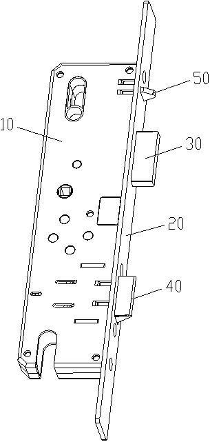
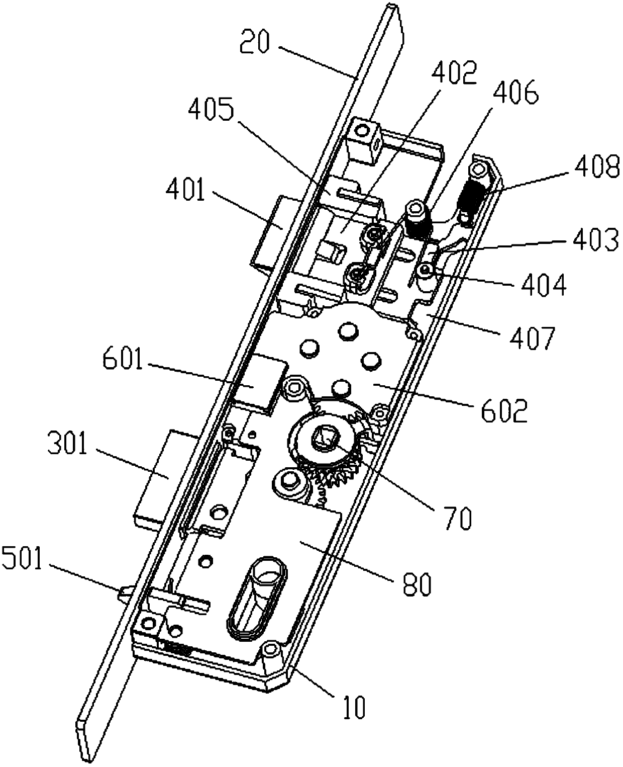
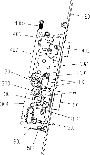
[0037] Such as Figure 1~3As shown, the present invention provides a fully automatic lock body, which includes a lock housing 10, a lock body side plate 20, a main tongue assembly 30, a rolling tongue assembly 40, a detection assembly 50, a driving device 60, a logic gear set 70 and a programmable Among them, the control circuit board 80, the lock body side plate 20 is placed on the side of the lock housing 10 for the installation of the lock body; the main tongue assembly 30 is placed inside the lock body 10 for locking the door body; the rolling tongue assembly 40 is placed One side of the main tongue assembly 30 is used to assist the main tongue assembly 30 to lock the door body; the detection assembly 50 is placed on the other side of the main tongue assembly 30 for detecting the position of the main tongue assembly 30 when it is in a stable state; the driving device 60 is placed between the main tongue assembly 30 and the rolling tongue assembly 40 to provide power for th...


PUM


Abstract

The invention particularly discloses a full-automatic lock body. The full-automatic lock body comprises a lock housing, a lock body side plate, a main tongue assembly, a rolling tongue assembly, a detection assembly, a driving device, a logic gear set and a programmable control circuit board, wherein the lock body side plate is arranged on one side of the lock housing and is used for mounting thelock body; the main tongue assembly is arranged on the inner side of the lock body and is used for locking a door body; the rolling tongue assembly is arranged on one side of the main tongue assemblyand is used for assisting the main tongue assembly to lock the door body; the detection assembly is arranged on the other side of the main tongue assembly and is used for detecting the position of themain tongue assembly in a stable state; the driving device is arranged between the main tongue assembly and the rolling tongue assembly and is used for providing power for the main tongue assembly; the logic gear set is arranged between the main tongue assembly and the driving device and is used for transmitting the power of the driving device to the main tongue assembly; and the programmable control circuit board is used for controlling the working state of the driving device. The full-automatic lock body is compact in size, reliable in work, flexible and convenient to use and high in automation degree.

Description

technical field [0001] The invention relates to the technical field of door locks, in particular to a fully automatic lock body. Background technique [0002] At present, action locks are gradually emerging in the smart lock market. One of the methods is: when the correct password or fingerprint and other information are input, the lock tongue can simulate the action of opening the door with a key through the group drive of the motor on the panel to achieve the effect of automatic unlocking. , but this automatic unlocking method has great disadvantages. The first generation of products adopts high-power output motors and gear sets to adapt to different door installation environments and deformations. In this case, a higher voltage power supply must be used ( Mostly use lithium battery packs), high power consumption, and many problems such as uneven quality of lithium batteries; because the motor set is located in the panel, customers can use different traditional mechanical ...

Claims


Application Information

Patent Timeline
Patent Type & Authority Applications(China)
IPC IPC(8): E05B63/14E05B15/10E05B47/00E05B15/04
CPCE05B15/04E05B15/10E05B47/0012E05B47/026E05B63/146E05B2047/0013E05B2047/002E05B2047/0069
Inventor 冼东海陆小强叶健聪
Owner GUANGDONG LEVEL INTELLIGENT LOCK INDAL
Features
  • R&D
  • Intellectual Property
  • Life Sciences
  • Materials
  • Tech Scout
  • Unparalleled Data Quality
  • Higher Quality Content
  • 60% Fewer Hallucinations
Learn More