Power transformer with high wire clamping strength

A power transformer, a high-strength technology, applied in the field of transformers, can solve the problems of inability to guarantee the degree of stability, take a certain amount of time, and low service life, so as to improve convenience, reduce operation difficulty, and increase service life.

Inactive Publication Date: 2020-02-14
衡阳市华仪电力互感器有限公司
View PDF3 Cites 1 Cited by
  • Summary
  • Abstract
  • Description
  • Claims
  • Application Information

AI Technical Summary

Problems solved by technology

[0002] Transformers, also known as instrument transformers, are collectively referred to as current transformers and voltage transformers. They convert high voltages into low voltages and large currents into small currents for measurement or protection systems. Or large current is transformed into standard low voltage or standard small current in proportion to realize the standardization and miniaturization of measuring instruments, protection equipment and automatic control equipment. Safety, most of the power transformers with high clamping strength in the prior art are not easy to install, and the user needs to spend a certain amount of time to operate, and the stability after installation cannot be guaranteed, the service life is low, and it is difficult to meet the multi-directional needs. Therefore, we have proposed a power transformer with high clamping strength to solve the problems raised in the above-mentioned background technology

Method used


Image

  • Power transformer with high wire clamping strength
  • Power transformer with high wire clamping strength
  • Power transformer with high wire clamping strength

Examples


Embodiment Construction

[0017] The following will clearly and completely describe the technical solutions in the embodiments of the present invention with reference to the accompanying drawings in the embodiments of the present invention. Obviously, the described embodiments are only some, not all, embodiments of the present invention. Based on the embodiments of the present invention, all other embodiments obtained by persons of ordinary skill in the art without making creative efforts belong to the protection scope of the present invention.

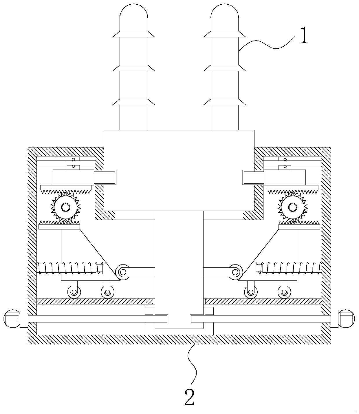
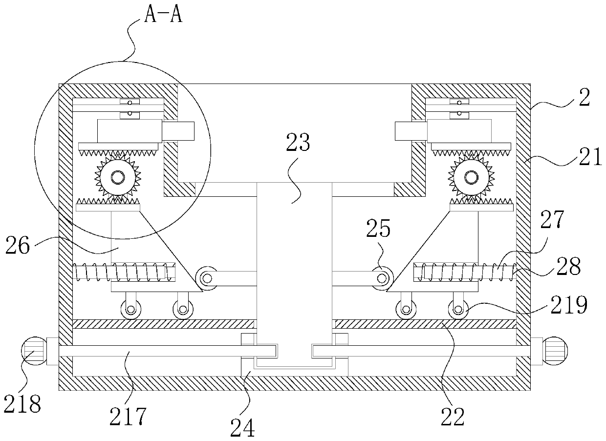
[0018] see Figure 1-3 , a power transformer with high clamping strength, including a power transformer body 1 and a mounting mechanism 2, the power transformer body 1 is arranged in a groove on the top of the mounting mechanism 2.

[0019] The installation mechanism 2 includes a housing 21, the inner wall of the housing 21 is fixedly connected with a partition 22, the inside of the housing 21 is provided with a connecting column 23, the top of the connecting ...


PUM


Abstract

The invention discloses a power transformer with high wire clamping strength. The transformer comprises a power transformer body and a mounting mechanism, wherein the power transformer body is arranged in a groove at the top of the mounting mechanism, the mounting mechanism comprises a shell, a partition plate is fixedly connected with an inner wall of the shell, a connecting column is arranged inthe shell, a top end of the connecting column is fixedly connected with the bottom of the power transformer body, an inserting groove is fixedly connected with a middle point of the bottom of the inner wall of the shell, a bottom end of the connecting column sequentially penetrates through the partition plate and an inserting groove from top to bottom and extends into the inserting groove to be connected with the inserting groove in an inserted mode, and rollers are fixedly installed on the left side and the right side of the connecting column above the partition plate. The power transformeris advantaged in that the power transformer is reasonable in structural design, the transformer can be conveniently and rapidly installed, operation difficulty of workers is reduced, the stability degree after installation can be guaranteed, the service life is prolonged, and then the multi-directional requirements are met.

Description

technical field [0001] The invention relates to the technical field of transformers, in particular to a power transformer with high clamping strength. Background technique [0002] Transformers, also known as instrument transformers, are collectively referred to as current transformers and voltage transformers. They convert high voltages into low voltages and large currents into small currents for measurement or protection systems. Or large current is transformed into standard low voltage or standard small current in proportion to realize the standardization and miniaturization of measuring instruments, protection equipment and automatic control equipment. Safety, most of the power transformers with high clamping strength in the prior art are not easy to install, and the user needs to spend a certain amount of time to operate, and the stability after installation cannot be guaranteed, the service life is low, and it is difficult to meet the multi-directional needs. Therefor...

Claims


Application Information

Patent Timeline
Patent Type & Authority Applications(China)
IPC IPC(8): H01F38/20
CPCH01F38/20
Inventor 李志祥董宏勇谭运春刘利群
Owner 衡阳市华仪电力互感器有限公司
Why Eureka
Try Eureka