

Mechanical fixture used for steel pipe cutting
A kind of machinery and fixture technology, applied in the field of mechanical fixtures for steel pipe cutting, can solve the problems of steel pipe falling off, difficult manpower to grasp, and reduce work efficiency, etc., to achieve the effect of increasing clamping strength, increasing fixing effect, and improving comprehensiveness
- Summary
- Abstract
- Description
- Claims
- Application Information
AI Technical Summary
Problems solved by technology
Method used
Image

Examples
Embodiment Construction
[0014] The following will clearly and completely describe the technical solutions in the embodiments of the present invention with reference to the accompanying drawings in the embodiments of the present invention. Obviously, the described embodiments are only some, not all, embodiments of the present invention.
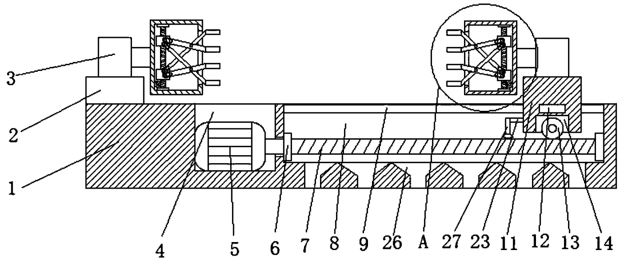
[0015] refer to Figure 1-2 , a mechanical fixture for cutting steel pipes, comprising a base 1, a fixed block 2 and a moving block 11 are respectively provided on both sides of the upper end of the base 1, and a moving groove 8 matching the moving block 11 is provided on the upper end of the base 1, and the moving block 11 Two sliding blocks 12 are arranged symmetrically on both sides of the outer wall, and the two sides of the inner wall of the moving groove 8 are provided with a chute 9 matching the sliding block 12, which can reduce the friction between the moving block 11 and the moving groove 8, and facilitate sliding and moving. The bottom of the groove 8 is e...
PUM
 Abstract
Description
Claims
Application Information