Crystal marking machine

A marking machine and crystal technology, which is applied to power transmission devices, printing, transfer materials, etc., can solve the problems of insufficient movement of the marking position of the picture frame, increase the workload of operators, and affect the overall appearance of the product, so as to increase the fixed effect. , Simple structure, low cost effect

Inactive Publication Date: 2016-12-07
CRYSTAL SHINE GLASS & CRAFT MFR
View PDF15 Cites 2 Cited by
  • Summary
  • Abstract
  • Description
  • Claims
  • Application Information

AI Technical Summary

Problems solved by technology

[0002] Marking machine refers to a kind of equipment that prints out fixed exquisite patterns, trademarks and characters on commodities. There are many types, the most common ones are pneumatic marking machine, electromagnetic marking machine and electrochemical marking machine. The accuracy of these types of marking machines is not enough, and the printing effect is poor, which will affect the overall appearance of t

Method used


Image

  • Crystal marking machine
  • Crystal marking machine
  • Crystal marking machine

Examples


Embodiment Construction

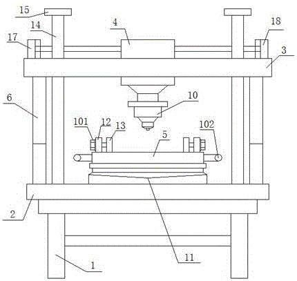
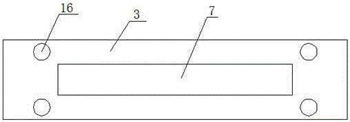
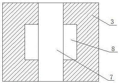
[0016] refer to figure 1 , figure 2 , image 3 and Figure 4 A crystal marking machine, including a frame 1, a support plate 2, a beam 3 and a moving block 4, the support plate 2 is fixed on the frame 1, and two hydraulic lifting rods are symmetrically arranged on the support plate 2 6. The crossbeam 3 is erected on the upper ends of the two hydraulic lifting rods 6, and the crossbeam 3 is provided with a moving groove 7 which is convenient for the moving block 4 to slide left and right, and the crossbeam 3 on both sides of the chute 7 is provided with a chute 8. The moving block 4 is provided with a slider 9 that slides in cooperation with the chute 8, the lower part of the moving block 4 is provided with an infrared marking head 10, and the middle part of the upper part of the support plate 2 is provided with a rotating mechanism 11. A workbench 5 is fixed on the output end of the upper part of the rotating mechanism 11, and two fixed plates 12 are arranged symmetrically...


PUM


Abstract

The invention discloses a crystal marking machine which comprises a machine frame, a supporting plate, a cross beam and a movable block. The supporting plate is fixed to the machine frame. Two hydraulic lifting rods are symmetrically arranged on the supporting plate. The cross beam is erected at the upper ends of the two hydraulic lifting rods. A moving groove which allows the movable block to slide leftwards and rightwards conveniently is formed in the cross beam. Sliding grooves are formed in the portions, on the two sides of the moving groove, of the cross beam. A sliding block which slides in cooperation with the sliding grooves is arranged on the movable block. An infrared marking head is arranged on the lower portion of the movable block. A rotation mechanism is arranged in the middle of the upper portion of the supporting plate. A workbench is fixed to the output end of the upper portion of the rotation mechanism. Two fixing plates are symmetrically arranged on the workbench. Positioning plates used for fixing a crystal are arranged on the portions, on the inner sides of the two fixing plates, of the workbench. Guiding rods are symmetrically arranged on the supporting plate, penetrate through the cross beam and extend to the upper portion of the cross beam. A crystal photo frame is fixed firmly and reliably, the marking effect is good, and the working efficiency of operators is improved.

Description

technical field [0001] The invention relates to a crystal marking machine. Background technique [0002] Marking machine refers to a kind of equipment that prints out fixed exquisite patterns, trademarks and characters on commodities. There are many types, the most common ones are pneumatic marking machine, electromagnetic marking machine and electrochemical marking machine. The accuracy of these types of marking machines is not enough, and the printing effect is poor, which will affect the overall appearance of the product. Nowadays, infrared marking machines have appeared on the market, but the existing infrared marking machines are marking crystal picture frames. At the same time, the fixing effect of the picture frame is poor, the marking position of the picture frame is not moved enough, the marking accuracy is not enough, and the marking effect is poor, which increases the workload of the operator, which will bring losses to the user. Contents of the invention [00...

Claims


Application Information

Patent Timeline
IPC IPC(8): B41J25/304B41J25/24
CPCB41J25/304B41J25/24
Inventor 张必军
Owner CRYSTAL SHINE GLASS & CRAFT MFR
Why Eureka
Try Eureka