Worker management system, worker management apparatus and worker management method

a management system and worker technology, applied in the field of worker management system, worker management apparatus and worker management method, can solve the problems of individual workers not being able to achieve maximum work efficiency, inconvenient to carry out in practice, and workers not being able to take on new tasks, etc., to and facilitate the detection of the exact work area

Inactive Publication Date: 2005-09-22
TOKYO ELECTRON LTD
View PDF11 Cites 111 Cited by
  • Summary
  • Abstract
  • Description
  • Claims
  • Application Information

AI Technical Summary

Benefits of technology

[0180] It is to be noted that in the worker management systems, the worker management apparatuses and the worker management methods described above, the worker detection part may each include a receiver that receives electromagnetic waves transmitted from transmitters carried by the individual workers, the transmitters may each be set so as to transmit an electromagnetic wave with a frequency unique to a specific worker and the worker position identification part may determine the worker detection part having received an electromagnetic wave with the frequency assigned to a worker undergoing a work area detection and identify the work area in which the worker detection part is installed as the work area where the worker is present. Since these features facilitate the detection of the exact work area where a given worker is currently located, the task that the worker is currently performing can be detected with ease based upon the work area information.
[0181] Alternatively, in the worker management systems, the worker management apparatuses and the worker management methods described above, the worker detection part may each include a receiver that receives electromagnetic waves transmitted from transmitters carried by individual workers, the transmitters may each be set so as to transmit an electromagnetic wave carrying identification information that can be used to identify a specific worker, and the worker position identification part may obtain worker identification information from the worker detection part, determine the worker detection part having received the worker identification information corresponding to a worker undergoing a work area detection and identify the work area in which the worker detection part is installed as the work area where the worker is present. These features, too, facilitate the detection of the exact work area where a given worker is currently located, and the task that the worker is currently performing can be detected with ease based upon the work area information.
[0182] Furthermore, in conjunction with the worker management systems, the worker management apparatuses and the worker management methods described above, a task information acquisition part for obtaining worker task information from work devices installed in the work areas may be further provided, and the current task identification part may obtain task information (task information related to the device and may also be referred to as “device information” in the specification) originating at a work device at which the worker is performing a task from the task information acquisition part in addition to the work area information indicating the work area identified as the work area in which the worker is currently present and identify the current task being performed by the worker based upon the area information and the task information. These features enable a fairly detailed detection of task contents (e.g., a specific classified task category such as troubleshooting or a normal operation task) based upon the work area information indicating the work area where a given worker is currently located, and further enable an even more detailed detection of the task contents (e.g., electrical system troubleshooting work or mechanical system troubleshooting) based upon the task information.

Problems solved by technology

The management of workers having varying skills is a challenging undertaking, and unless work is assigned efficiently, individual workers will not be able to achieve maximum work efficiency.
While it is ideal to select and give instructions to an optimal worker to perform a given operation with the right timing, this is not easily accomplished in practice.
For instance, if a new task that must be performed arises while a worker is engaged in a different operation, the worker cannot be instructed to take on the new task.
In this situation, unless the details of the operation the worker is currently performing are ascertained, a decision as to whether or not to instruct him to interrupt the current operation to take on the new task cannot be made.
However, a worker with the skills needed to perform the new task may not always be available.
Since many different types of work are performed at a semiconductor manufacturing plant and the like as described above, it is extremely difficult to keep abreast of the specific tasks the individual workers are currently performing.
However, this technology only makes it possible to identify different types of workers (classified worker categories) such as operators and engineers and the exact task a given worker is currently performing cannot be detected through the technology.
However, a problem arises in the worker ID entry system in that types of work that do not require screen input operations or the like cannot be identified.
However, workers may be significantly slowed down if they have to enter task contents each time they take on a new task, which may result in lowered work efficiency.
In particular, in an emergency such as a fire or a machine failure, workers need to perform troubleshooting as soon as possible and for this reason, mandating the task contents entry for purposes of worker management is not appropriate.

Method used


Image

  • Worker management system, worker management apparatus and worker management method
  • Worker management system, worker management apparatus and worker management method
  • Worker management system, worker management apparatus and worker management method

Examples


first embodiment

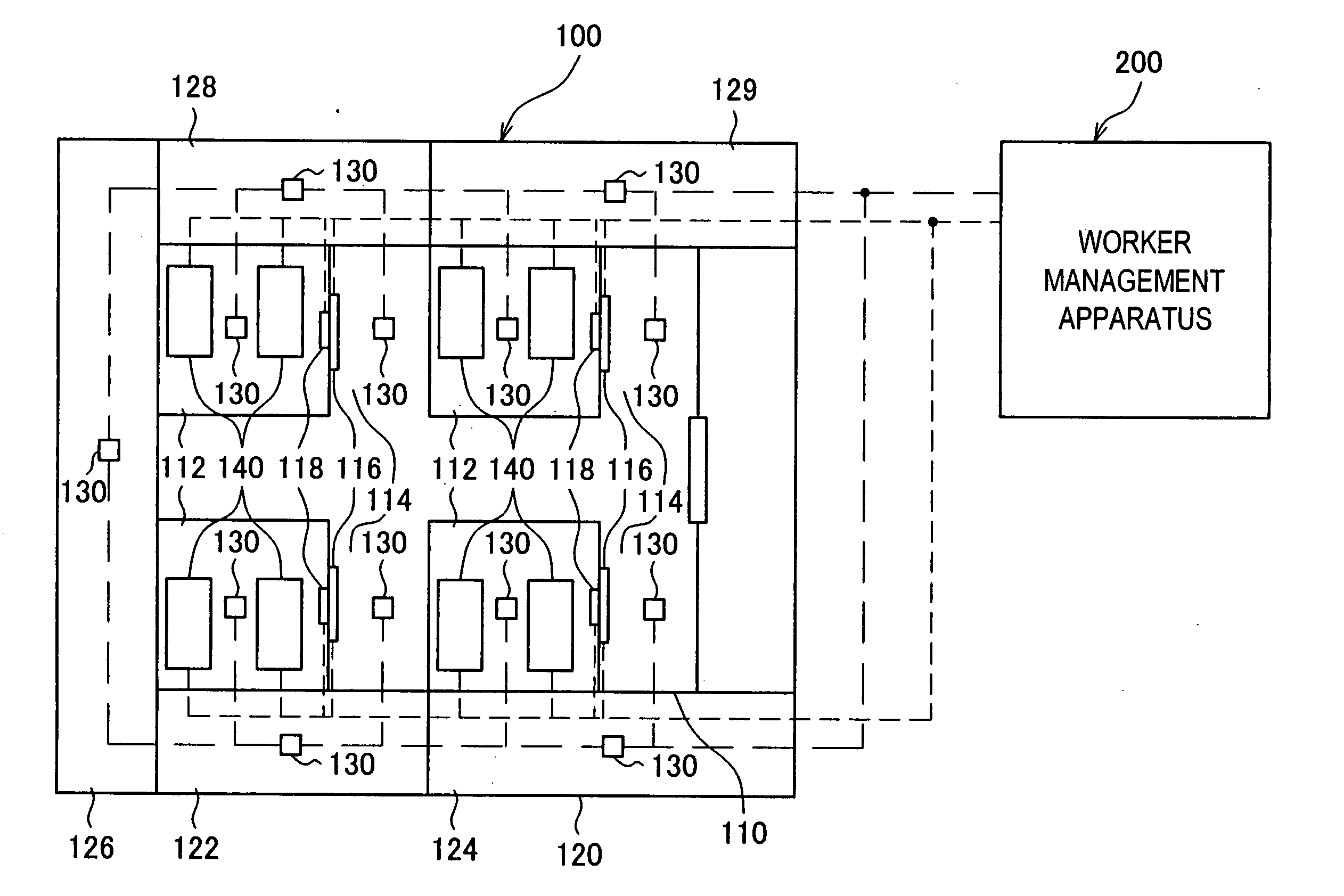
[0204] First, the worker management system achieved in the first embodiment by adopting the present invention in a semiconductor manufacturing plant is explained in reference to drawings. FIG. 1 shows an example of a floor plan inside a semiconductor manufacturing plant 100 which constitutes the work site in the embodiment by way of showing the overall structure adopted in the worker management system at the semiconductor manufacturing plant. Reference numeral 200 indicates a worker management apparatus.

[0205] As shown in FIG. 1, the area inside the semiconductor manufacturing plant 100 is largely divided into two areas, i.e., a clean room area 110 and an area 120 excluding the clean room (hereafter referred to as a “non-clean room area”).

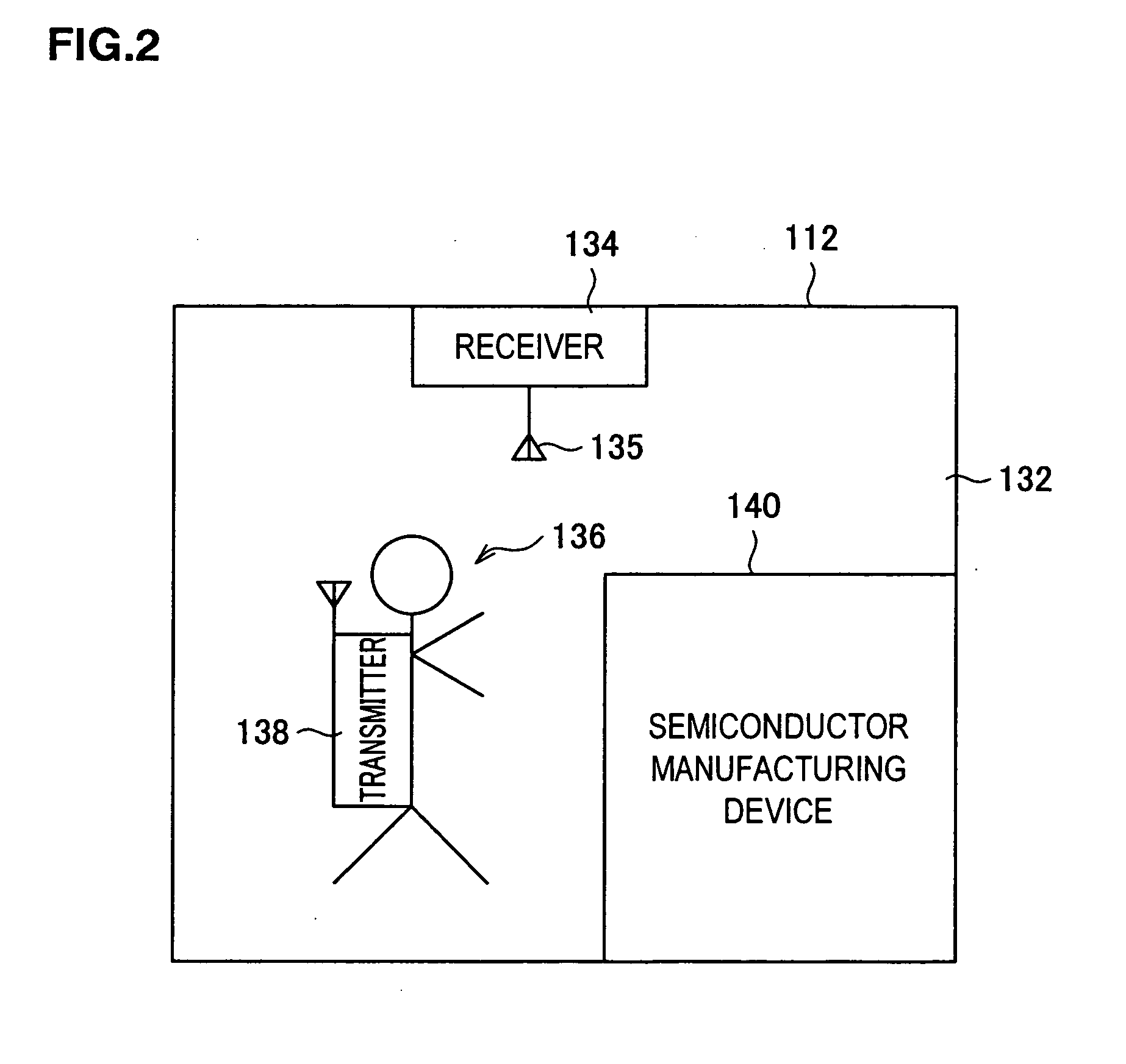
[0206] The clean room area 110 is further divided into a plurality of equipment room areas 112 and an area other than the equipment rooms (hereafter referred to as a “non-equipment room area”). Semiconductor manufacturing devices 140 such as proc...

second embodiment

[0290] Next, the worker management system achieved in the second embodiment by adopting the present invention in a semiconductor manufacturing plant is explained in reference to drawings. It is to be noted that since the structural features shown in FIGS. 1 through 10 also apply to the second embodiment, a repeated explanation thereof is omitted. In addition, the same reference numerals are assigned to components similar to those in the first embodiment to preclude the necessity for a detailed explanation thereof.

[0291] Another specific example of new task assignment processing that may be executed at the worker management apparatus 200 in the second embodiment is now explained in reference to FIGS. 15 and 16. It is to be noted that the processing executed in the embodiment may be typically achieved in the form of a program recorded in a recording medium such as a hard disk device.

[0292] The new task assignment processing executed in the second embodiment differs from the processi...

third embodiment

[0304] Next, the worker management system achieved in the third embodiment by adopting the present invention in a semiconductor manufacturing plant is explained in reference to drawings. It is to be noted that since the structural features shown in FIGS. 1 through 10 also apply to the third embodiment, a repeated explanation thereof is omitted. In addition, the same reference numerals are assigned to components similar to those in the first embodiment to preclude the necessity for a detailed explanation thereof. It is to be noted that the processing executed in the embodiment may be typically achieved in the form of a program recorded in a recording medium such as a hard disk device.

[0305] Processing executed to create a task database is now explained in reference to FIG. 17 as an example of the task information storage part included in the worker management apparatus 200 achieved in the third embodiment. The task database is used when preparing a daily task report for each worker,...


PUM


Abstract

A worker management system, which includes a plant 100 divided into a plurality of work areas each in correspondence to specific task contents, a database 220 having stored therein task identification information correlating each work area 112 with contents of tasks performed therein and worker detection sensors 130 installed in each work area, identifies the specific work area where a worker is currently located based upon outputs from the worker detection means and then identifies the task currently performed by the worker based upon the task identification information. Based upon the current task thus identified, a decision is made as to whether the worker should continue the current task or be assigned a new task and an instruction for task execution is issued to the worker. Therefore the identification of current tasks, the assignment of a new task and the task reassignment are facilitated to improve the work efficiency.

Description

CROSS REFERENCE TO RELATED APPLICATIONS [0001] This is a continuation application of PCT International Application No. PCT / JP03 / 13841 filed on Oct. 29, 2003, which claimed priority of Japanese Patent Application No. JP2002-314866 filed on Oct. 29, 2002. The contents of these applications are incorporated herein by reference in their entirety.BACKGROUND OF THE INVENTION [0002] 1. Field of the Invention [0003] The present invention relates to a worker management system, a worker management apparatus and a worker management method. [0004] 2. Description of the Related Art [0005] At a work site such as a semiconductor manufacturing plant, various types of tasks are performed in different areas that include an equipment room where semiconductor manufacturing devices and the like are installed in a clean room. For instance, while an input operation for the semiconductor device production needs to be performed outside the equipment room and a troubleshooting operation for correcting an err...

Claims


Application Information

Patent Timeline
Patent Type & Authority Applications(United States)
IPC IPC(8): G06Q10/00
CPCG06Q10/063112G06Q10/063114G06Q10/10G06Q10/06316G06Q10/063116Y10S707/99943
Inventor IWASAKI, KENYANISHIKAWA, HIROSHI
Owner TOKYO ELECTRON LTD
Why Eureka
Try Eureka