Dynamic bias current generator and related electronic device

A technology of bias current and generator, which is applied in the direction of electronic switches, instruments, electrical components, etc. It can solve the problems of not being able to obtain low power consumption and high-speed performance at the same time, and achieve the effects of low power consumption, increased response speed, and improved speed

Active Publication Date: 2020-04-07
ARTERY TECH CO LTD
View PDF5 Cites 0 Cited by
  • Summary
  • Abstract
  • Description
  • Claims
  • Application Information

AI Technical Summary

Problems solved by technology

Therefore, low power consumption and high-speed performance cannot be obtained at the same time in the related art.

Method used


Image

  • Dynamic bias current generator and related electronic device
  • Dynamic bias current generator and related electronic device
  • Dynamic bias current generator and related electronic device

Examples


Embodiment Construction

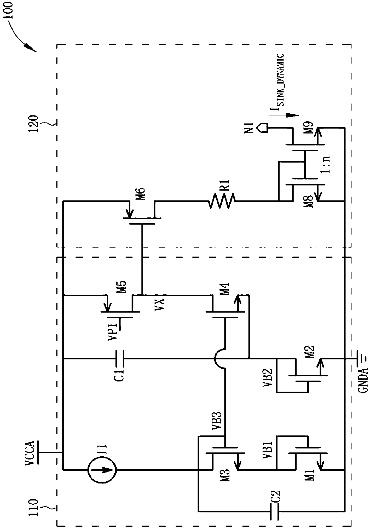
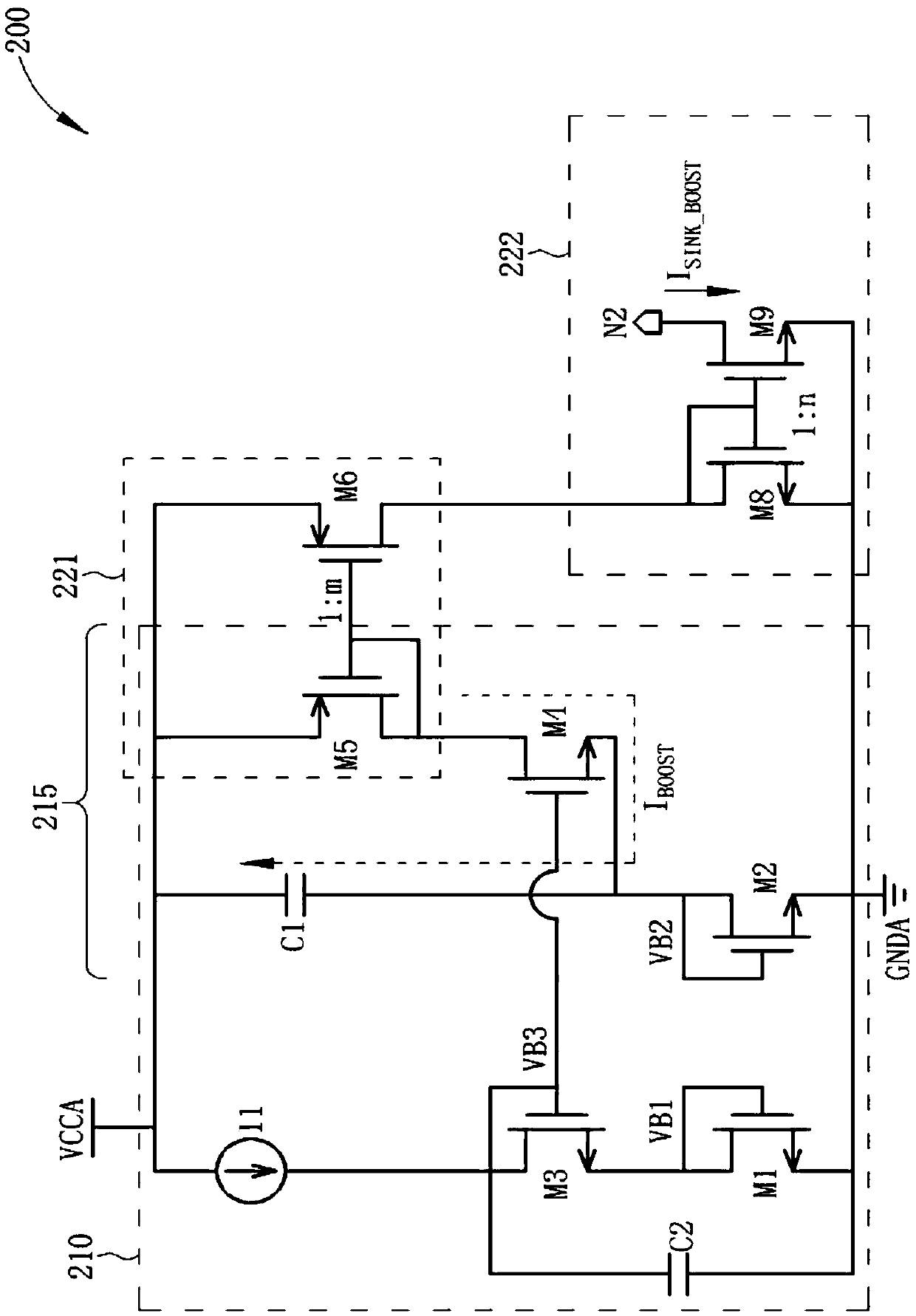
[0034] Various embodiments of the present invention disclose a dynamic bias current generator, wherein the dynamic bias current generator may include a detection circuit and at least one current generating circuit (eg, one or more current generating circuits). For easy understanding, the dynamic bias current generator can be set in a reset control circuit in an electronic device, especially, can be used as a comparator to monitor the power supply voltage to perform reset control on the electronic device. The dynamic bias current generator can generate dynamic bias current to increase the response speed of the comparator, so that the electronic device can simultaneously obtain low power consumption and high-speed performance. Examples of such dynamic bias current generators may include (but are not limited to): figure 1 The dynamic bias current generator 100 is shown with figure 2 The dynamic bias current generator 200 is shown. figure 1 The architecture shown is the same as...


PUM


Abstract

The invention discloses a dynamic bias current generator and a related electronic device. The dynamic bias current generator comprises a detection circuit and a current generation circuit. The detection circuit detects a power supply voltage to generate a detection signal, and comprises a current source and a first group of transistors located on a first path; a second group of transistors on thesecond path, control terminals of respective transistors of the first and second groups of transistors being coupled to each other; a first capacitor coupled to the supply voltage and other terminalsof the transistors in the second set of transistors; and a second capacitor coupled to control terminals of respective transistors of the first and second groups of transistors and a ground voltage. The current generation circuit includes: a plurality of transistors that generate a dynamic bias current according to a detection signal. The dynamic bias current can be used for increasing the reaction speed of the comparator and used in a power-down reset detection circuit. The advantages of the dynamic bias current generator are that the dynamic bias current generator enables the electronic device to obtain low power consumption and high speed performance at the same time.

Description

technical field [0001] The invention relates to low power consumption circuit design, in particular to a dynamic bias current generator and related electronic devices. Background technique [0002] Reset (reset) control mechanisms such as power-on reset (power-on reset, POR), power-down reset (powerdown reset, PDR), brown-out reset (brown-out reset, BOR), etc. are very important in circuit design. important topic. For example, when powering up an electronic system, it takes a certain length of time for the power supply to stabilize the voltage and reach its steady state value. During such transitions, if no reset command is provided, it is generally not possible to define the initial state of the storage elements and thus the circuit behavior of the entire electronic system. [0003] According to the related art, when attempting to directly apply the reset control mechanism to the design of low power consumption circuits, some disturbing problems are often encountered. Fo...

Claims


Application Information

Patent Timeline
Patent Type & Authority Applications(China)
IPC IPC(8): G05F1/56
CPCG05F1/56G05F3/24H03K17/22
Inventor 王维铁郝报田李超
Owner ARTERY TECH CO LTD
Why Eureka
Try Eureka