
Round tube outer wall crawling robot
A technology of crawling robots and round pipes, applied in the field of robotics, can solve problems such as difficult maintenance, unmanned development, and easy jamming
- Summary
- Abstract
- Description
- Claims
- Application Information
AI Technical Summary
Problems solved by technology
Method used
Image

Examples
Embodiment Construction
[0023] The present invention will be described in detail below in conjunction with the accompanying drawings and specific embodiments.
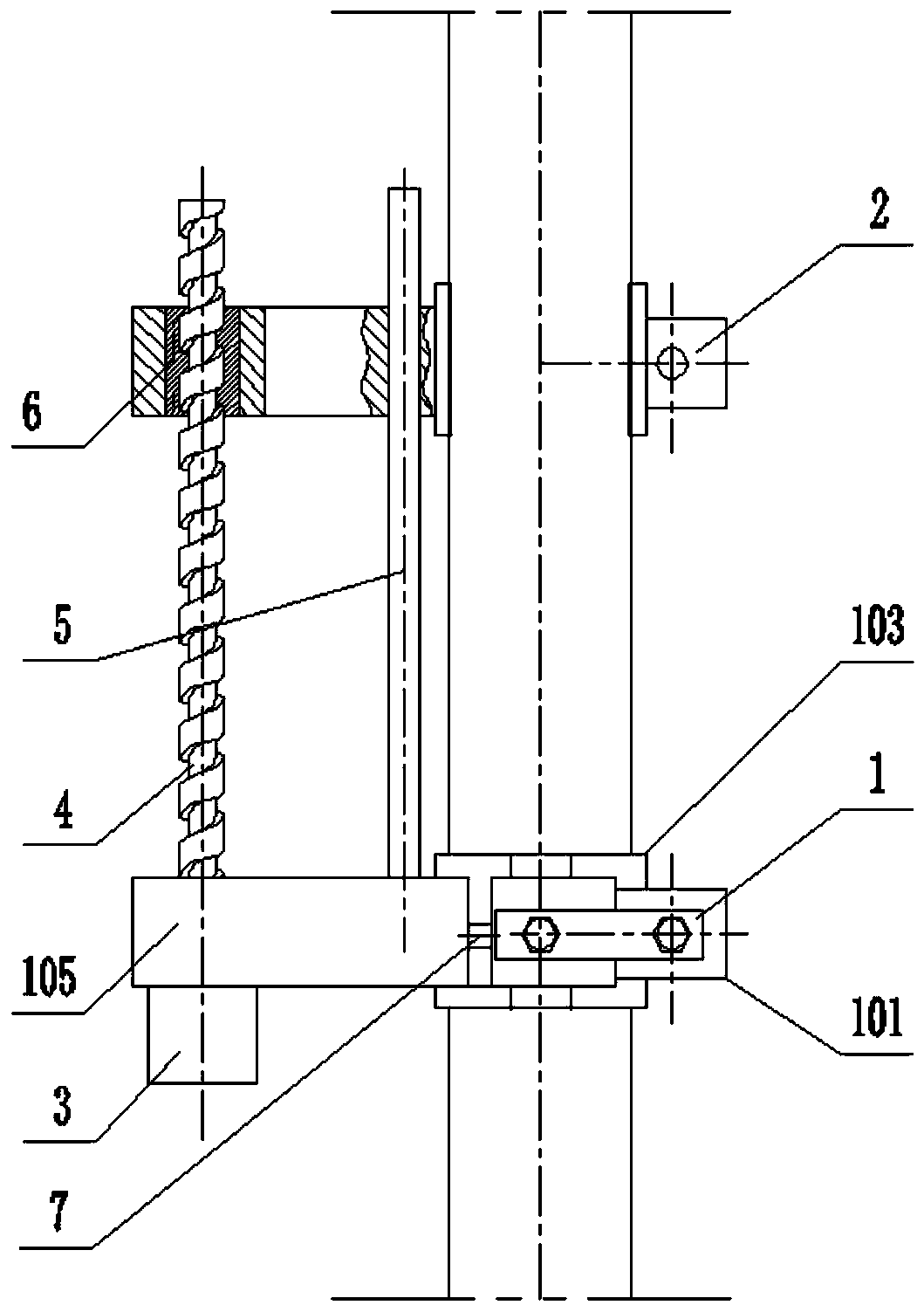
[0024] The present invention is a circular tube outer wall crawling robot, such as figure 1 As shown, it includes two front holding devices 2 and rear holding devices 1 arranged side by side. The rear holding device 1 and the front holding device 2 are jointly hinged with a crawling device, and the crawling device includes a rear holding device fixed on the 1 Servomotor 3, servomotor 3 is connected with screw rod 4, is embedded with nut 6 in the position corresponding to screw rod 4 on the front holding device 2, and screw rod 4 stretches in the nut 6.
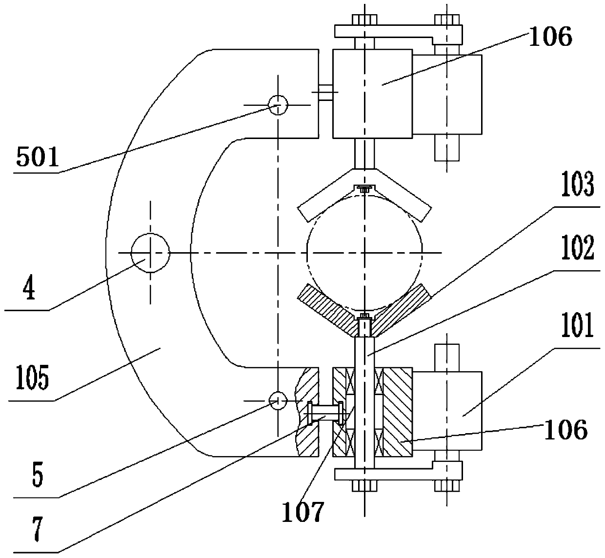
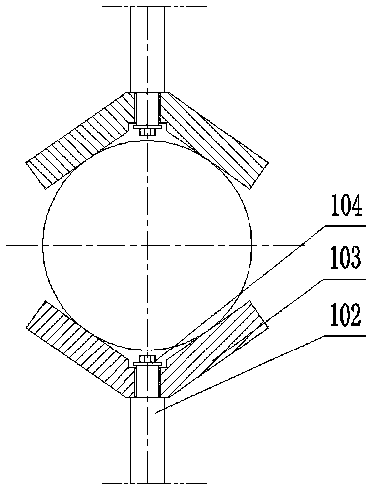
[0025] Such as figure 2 As shown, the front clamping device 2 and the rear clamping device 1 have the same structure, both of which include a shoe 105, the two ends of the shoe 105 are fixedly connected with a steering shaft 7, and the other end of the steering shaft 7 is hinged with a mani...
PUM
 Abstract
Description
Claims
Application Information