Electronic product display device

A technology for display devices and electronic products, applied in display stands, display hangers, display shelves, etc., can solve problems such as inability to conduct comprehensive observation, and achieve the effects of facilitating promotion and implementation, saving electric energy, and improving display capabilities

Active Publication Date: 2020-04-24
广东金石卖场建设有限公司
View PDF12 Cites 4 Cited by
  • Summary
  • Abstract
  • Description
  • Claims
  • Application Information

AI Technical Summary

Problems solved by technology

[0004] The purpose of the embodiments of the present invention is to provide an electronic product display device, aiming to solve the problem of inability to conduct comprehensive observation

Method used


Image

  • Electronic product display device
  • Electronic product display device
  • Electronic product display device

Examples


Embodiment 1

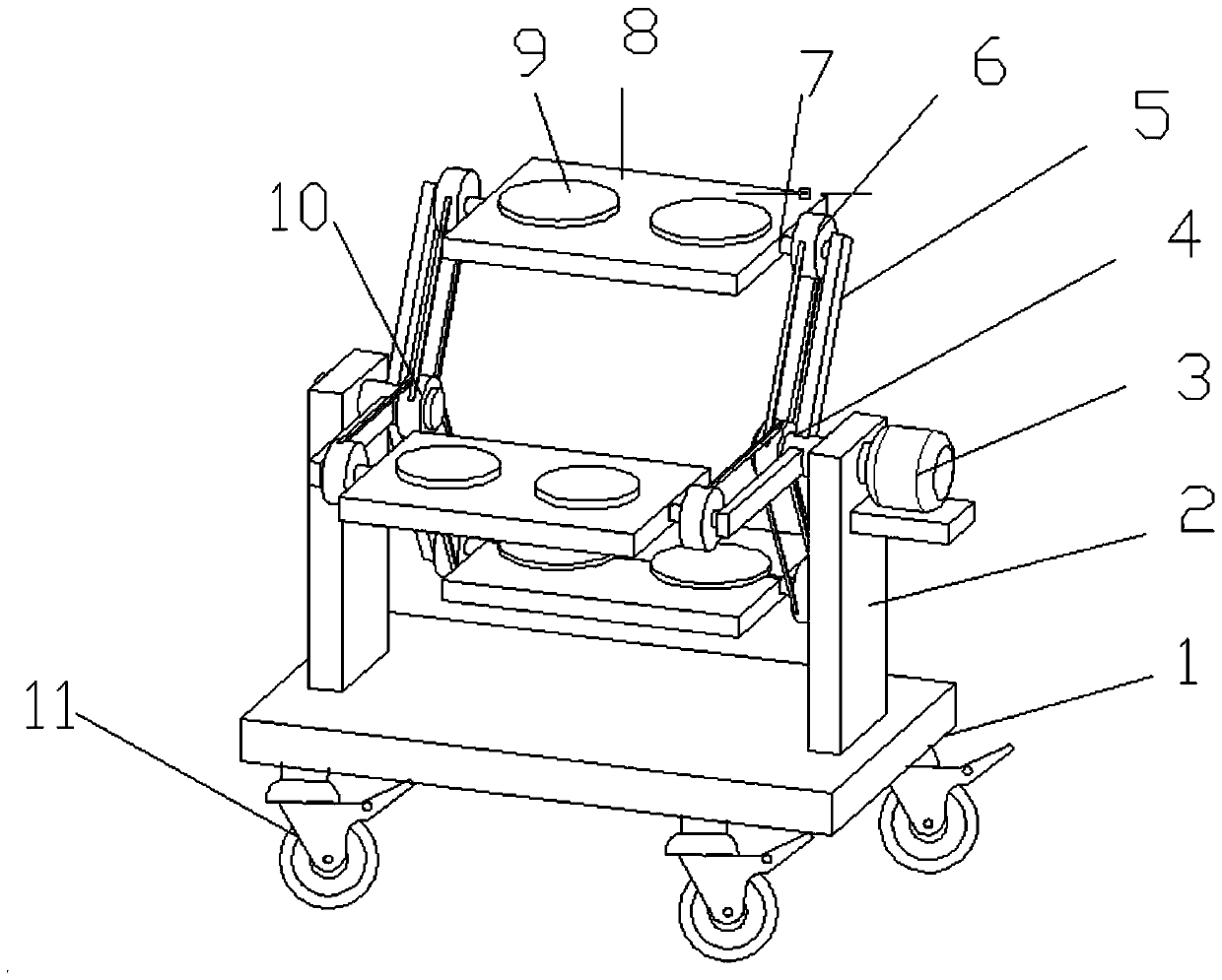
[0027] Please refer to Figure 1-3 , an electronic product display device, comprising a base 1 and a placement plate 8, the four corners of the bottom of the base 1 are provided with universal wheels 11, the universal wheels 11 are provided with brake plates, and the brake plates brake the universal wheels 11 Effect, the universal wheel 11 is set to facilitate the movement and fixing of the base 1. The left and right ends of the upper surface of the base 1 are fixedly provided with a column 2, and the inner side of the top of the column 2 is rotated to be provided with a rotating shaft 4, and one end of the rotating shaft 4 is connected with the motor 3 installed on the column 2, and driven by the motor 3, it rotates Axis 4 rotates. The side wall of the column 2 is provided with a motor cover so as to cover the motor 3 and protect the motor 3 while increasing the aesthetics of the device. The side wall of the rotating shaft 4 is fixedly connected to the inner end of the rota...

Embodiment 2

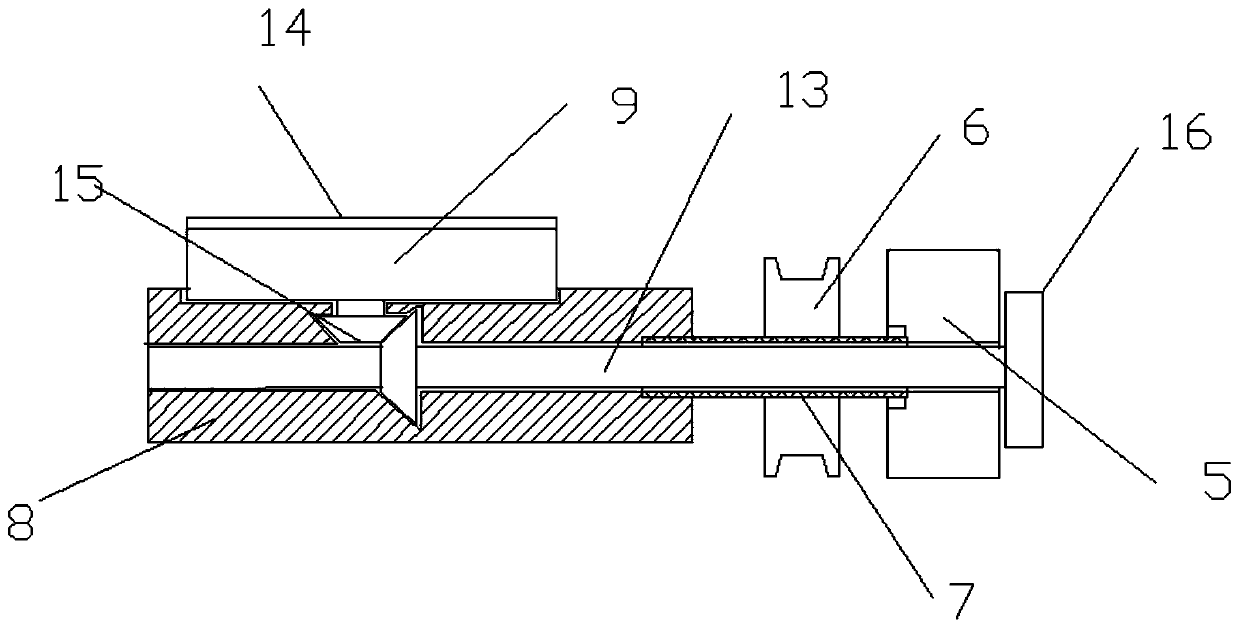
[0032] see Figure 4 On the basis of Embodiment 1, the rotating shaft 13 is transmitted through the transmission member 16, so that the rotating shaft 13 can be rotated relative to the placement plate 8. The transmission member 16 includes a second driving pulley 17 and a second driven pulley 18, and the second driving pulley Belt pulley 17 is coaxially fixedly connected on the rotating shaft 4 on the outside of rotating rod 5, and the second driven pulley 18 is coaxially fixedly connected with the outer end of rotating shaft 13, and the second driving pulley 17 and the second driven pulley 18 are connected by belts. Connect, the radius of rotation of the second driving pulley 17 is greater than the radius of rotation of the second driven pulley 18, so that the rotation speed of the rotating shaft 13 can be faster than the rotation speed of the placement plate 8, so that the placement table 9 is rotated. The outer side of the rotating rod 5 is also fixedly provided with a pull...

Embodiment 3

[0034] see Figure 5 , on the basis of Embodiment 1, the rotating shaft 13 is transmitted through the transmission member 16, so that the rotating shaft 13 can be rotated relative to the placement plate 8. The transmission member 16 includes a driving gear 19 and a driven gear 20, and the driving gear 19 is fixedly connected to the rotating shaft. On the inner wall of the outer column 2 of the shaft 4, the driven gear 20 is coaxially fixedly connected with the outer end of the rotating shaft 13, the driven gear 20 meshes with the driving gear 19, and the rotating sleeve shaft 7 rotates so that the driven gear 20 surrounds the driving gear 19 rotates, thereby makes rotating shaft 13 rotate, drives placement table 9 to rotate with this.


PUM


Abstract

The invention is applicable to the technical field of electronic products, and provides an electronic product display device. The device comprises a base and placing plates, stand columns are fixedlyarranged at left and right ends of the upper surface of the base, rotating shafts are rotatably arranged on the inner sides at the top of the stand columns, one ends of the rotating shafts are connected to motors installed on the stand columns, side walls of the rotating shafts are fixedly connected to the inner ends of rotating rods, the inner sides at the outer ends of the rotating rods are rotatably connected to the outer ends of rotating sleeve shafts, and the inner ends of the rotating sleeve shafts are fixedly connected to two ends of the placing plate; the rotating sleeve shafts are coaxially and fixedly connected to first driven belt wheels, the inner sides of the rotating rods are coaxially and fixedly connected to first driving belt wheels on the rotating shafts, the rotating shafts rotatably penetrates through the rotating sleeve shafts, placing tables are rotatably arranged on the upper surfaces of the placing plates, and the bottoms of the placing tables are connected to the rotating shafts through steering gear sets. The display device has the advantages of simple structure, low production cost, electric energy saving, high display capacity, high safety and good aesthetics, and is convenient to popularize and implement.

Description

technical field [0001] The invention belongs to the technical field of electronic products, in particular to an electronic product display device. Background technique [0002] With the development of society and the advancement of science and technology, electronic products have entered various households and fields. Electronic products are related products based on electric energy, mainly including: watches, smart phones, telephones, computers, mobile communication products, etc., because The early products were mainly based on electronic tubes, so they were called electronic products. In order to let customers better understand the products, merchants often put the products on display racks for people to observe and try them out. [0003] Chinese patent (publication number: 109090919 A, announcement date: 2018.12.28) discloses an electronic product display device, including a base, the left and right sides of the base are fixedly connected to uprights, and the left side o...

Claims


Application Information

Patent Timeline
Patent Type & Authority Applications(China)
IPC IPC(8): A47F7/02A47F7/00A47F5/025A47F5/03
CPCA47F5/025A47F5/03A47F7/02A47F7/022
Inventor 刘超慧李宇根
Owner 广东金石卖场建设有限公司
Why Eureka
Try Eureka