Method for deflating hydraulic acutating apparatus

A hydraulic actuation and actuator technology, which is applied in the direction of fluid pressure actuation device, transmission device control, fluid pressure actuation system components, etc., can solve problems such as foaming and the danger of air entering the system

Pending Publication Date: 2020-05-22
FTE汽车有限责任公司
View PDF9 Cites 2 Cited by
  • Summary
  • Abstract
  • Description
  • Claims
  • Application Information

AI Technical Summary

Problems solved by technology

The constant delivery of hydraulic fluid through the hydraulic pump presents a risk of air entering the system, e.g. due to foaming of the delivered hydraulic fluid

Method used


Image

  • Method for deflating hydraulic acutating apparatus
  • Method for deflating hydraulic acutating apparatus
  • Method for deflating hydraulic acutating apparatus

Examples


Embodiment Construction

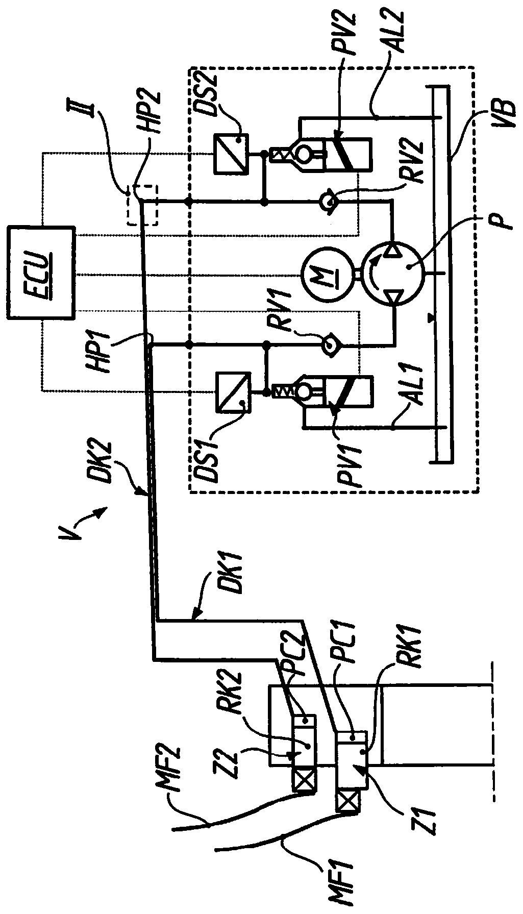
[0033] figure 1 A device V is shown for the hydraulic actuation of two friction clutches (not shown in detail), as is known in principle from the applicant's publication EP2532914A1. The device V comprises a pressure generator (in this case in the form of a dual-circuit hydraulic pump P) with an electric pump drive M, two pressure circuits DK1, DK2 hydraulically connected to the hydraulic pump P and for hydraulic fluid The reservoir VB, hydraulic fluid can be delivered from the reservoir VB through the hydraulic pump P in the pressure circuit DK1, DK2. Starting from the hydraulic pump P, each pressure circuit DK1, DK2 has a non-return valve RV1, RV2 which closes in the direction of the hydraulic pump P and an electromagnetically actuatable proportional throttle valve PV1, PV2 as a pressure regulator, by means of which The valves, the respective pressure circuits DK1 , DK2 , can be released in a defined manner towards the accumulator VB via the outlet lines AL1 , AL2 .

[003...


PUM


Abstract

The invention discloses a method for deflating a hydraulically actuated device for at least one friction clutch and / or at least one transmission actuator through a piston / cylinder arrangement connected to at least one pressure circuit. The hydraulic pressure is generated by the pressure generator and can be set by the pressure regulator and released to the reservoir via the discharge line. In thismethod, a deflation cycle with multiple circulation parts (ZAn) is performed. Each cycle starts from the pressure build-up phase (DAPn) and includes the subsequent pressure release phase (DEPn). In this case, the pressure in the pressure circuit builds slowly during the pressure build-up phase, and slowly drops again during the pressure release phase. In this way, quick deflation of such a devicethat can be performed in an automated manner is facilitated without additional device-related costs.

Description

technical field [0001] The invention generally relates to a method for deflating a device for hydraulic actuation of at least one friction clutch and / or at least one transmission actuator according to the preamble of claim 1 . The invention relates in particular to a device for the hydraulic actuation of a friction clutch in a transmission of a motor vehicle or a friction clutch in a multi-clutch transmission of a motor vehicle and / or for an actuator in an automatic transmission of a motor vehicle A hydraulically actuated device for deflation. [0002] When it is necessary to actuate in as flexible and friction-free a manner as possible and with the small installation space requirements of automatic shift transmissions (AST), double or multiple clutch transmissions (DCT) or separable distributor and differential transmissions with Such hydraulic actuation devices are widely used in modern motor vehicles for transmission actuators such as shift forks and shift bushings and (we...

Claims


Application Information

Patent Timeline
Patent Type & Authority Applications(China)
IPC IPC(8): F15B21/044F16H61/30
CPCF15B21/044F16H61/30F16H63/3023F16H63/3026F15B2211/20515F15B2211/20561F15B2211/50554F15B2211/6309F15B2211/7142F16H63/3043F15B21/04F16D2125/16
Inventor W.赫布纳
Owner FTE汽车有限责任公司
Why Eureka
Try Eureka