Integrated sewage lifting device

A technology for sewage lifting and equipment, applied in water conservancy projects, cleaning of open water surfaces, construction, etc., can solve the problems of high energy consumption of submersible pumps, poor rain and sewage collection effect, and increased separation difficulty, and achieve the goal of reducing installation conditions Restriction and difficulty of installation, simple structure, effect of increasing stability

Active Publication Date: 2020-07-24
SHANDONG HUALI WATER SUPPLY EQUIP CO LTD
View PDF7 Cites 3 Cited by
  • Summary
  • Abstract
  • Description
  • Claims
  • Application Information

AI Technical Summary

Problems solved by technology

[0003] The existing patent number CN106277608B proposes a CN106277608B, which uses structures such as filter chambers, chemical sedimentation tanks, activated carbon chambers, biological filter tanks, and water storage tanks to collect and process rain and sewage, but its various structures are scattered, resulting in high installation requirements , and the structure it contains cannot simply collect the rain pollution that has been floating in the water
[0004] The existing patent number CN105442686B proposes a self-cleaning integrated collection and delivery device for sewage and rainwater, through more than one submersible sewage pump, water inlet pipe, mesh trash rack with deflector or crushing character The structure such as grid realizes the collection of rain and sewage, but when the above device is used, it will use the submersible pump to collect a large amount of water and rain and sewage together, resulting in the mixing of rain and sewage floating in the water area with the water flow, which increases the difficulty of separation. The submersible pump While the energy consumption is large, the effect of collecting rainwater floating on the surface of the water area is not good

Method used


Image

  • Integrated sewage lifting device
  • Integrated sewage lifting device
  • Integrated sewage lifting device

Examples


Embodiment Construction

[0037] The following will clearly and completely describe the technical solutions in the embodiments of the present invention with reference to the accompanying drawings in the embodiments of the present invention. Obviously, the described embodiments are only some of the embodiments of the present invention, not all of them. Based on the embodiments of the present invention, all other embodiments obtained by persons of ordinary skill in the art without making creative efforts belong to the protection scope of the present invention.

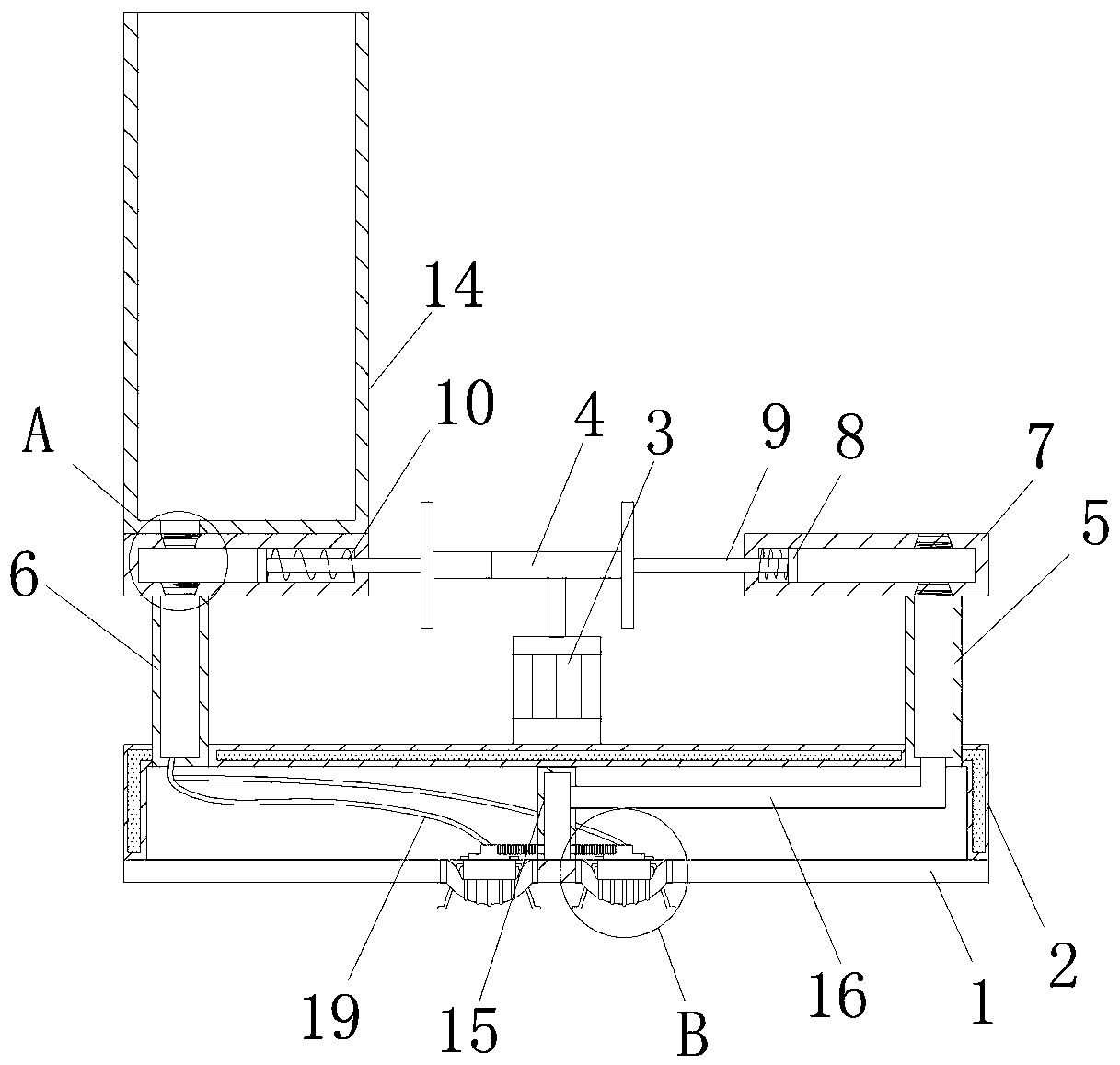
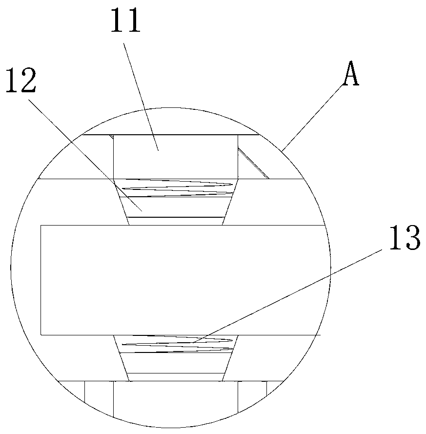
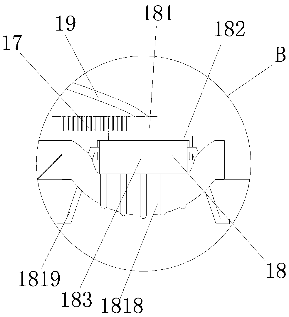
[0038] see Figure 1-11 , integrated sewage lifting equipment, including a bottom plate 1, a buoy 2 and a lifting device 18, the buoy 2 is a hollowed-out rectangular body with a bottom surface, the bottom plate 1 is fixedly connected to the bottom surface of the buoy 2, both sides of the top surface of the bottom plate 1 are hollowed out, and the lifting device The number of 18 is two and they are respectively socketed on the inner walls of both ...


PUM


Abstract

The invention relates to the technical field of sewage treatment, and discloses an integrated sewage lifting device. The device comprises a bottom plate, a floating cylinder and lifting devices, the floating cylinder is a rectangle with a hollow-out bottom face, the bottom plate is fixedly connected to the bottom face of the floating cylinder, the two sides of the top face of the bottom plate arein hollow-out states, the two lifting devices are mounted on the inner walls of the two sides of the bottom plates in a sleeving manner correspondingly, through the lifting devices, a sewage collecting bottle is used for digging rain sewage on the water area surface, the rain sewage is separated from water surface tension to be stacked on the sunken bottom face inner wall of the sewage collectingbottle, collecting and separating of the rain sewage on the water area surface can be achieved, water flowing serves as power, two sewage collecting plates can be driven to be in opening and closing track motion, the stacked rain sewage in the sewage collecting bottle is compressed, the volume of the rain sewage is reduced, the storage amount of the sewage collecting bottle is increased, the rainsewage density can be increased, the possibility that the rain sewage is flushed away by the water flow can be avoided, the sewage collecting plates are used for containing part of rain sewage, and the collecting space of the sewage collecting bottle for the rainwater can be widened.

Description

technical field [0001] The invention relates to the technical field of sewage treatment, in particular to integrated sewage lifting equipment. Background technique [0002] With the increasing environmental pollution in some areas, rainwater will be doped with various polluting substances and fall into the waters. The rain pollution doped with pollutants will float and collect on the surface of the waters due to its low density, forming a large area. The floating pollution of rainwater, and the collection of these rainwater floating on the water area has become an important issue. [0003] The existing patent number CN106277608B proposes a kind of CN106277608B, which uses structures such as filter chamber, chemical sedimentation tank, activated carbon chamber, biological filter tank and water storage tank to realize the collection and treatment of rain and sewage, but its various structures are scattered, resulting in high installation requirements , and the structure it co...

Claims


Application Information

Patent Timeline
IPC IPC(8): E02B15/10
CPCE02B15/10E02B15/106
Inventor 陈倩倩
Owner SHANDONG HUALI WATER SUPPLY EQUIP CO LTD
Why Eureka
Try Eureka