
Display device and charging control method applied to display device

A display device and display line technology, applied in static indicators, instruments, etc., can solve the problems of the deterioration of the charging rate of the distance source driver and the large difference between the upper half screen and the lower half screen, so as to reduce the difference in the charging rate and improve the charging rate. effect of time

Active Publication Date: 2020-07-31
TCL CHINA STAR OPTOELECTRONICS TECH CO LTD
View PDF8 Cites 2 Cited by
  • Summary
  • Abstract
  • Description
  • Claims
  • Application Information

AI Technical Summary

Problems solved by technology

[0003] The present application provides a display device, which solves the problem that the charging rate of pixel rows gradually deteriorates from near to far from the source driver, resulting in a large difference between the upper half screen and the lower half screen when the screen is displayed.

Method used


Image

  • Display device and charging control method applied to display device
  • Display device and charging control method applied to display device

Examples


Embodiment Construction

[0018] The technical solutions in the embodiments of the present application will be clearly and completely described below in conjunction with the drawings in the embodiments of the present application. Apparently, the described embodiments are only some of the embodiments of this application, not all of them. Based on the embodiments in this application, all other embodiments obtained by those skilled in the art without making creative efforts belong to the scope of protection of this application.

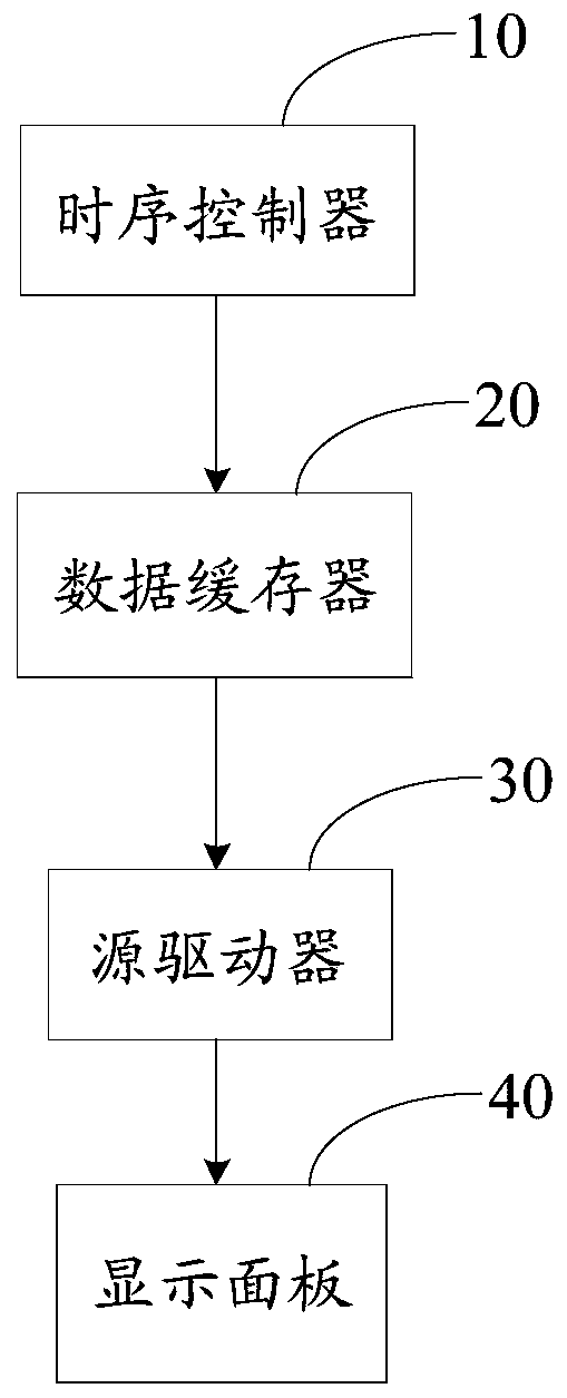
[0019] Such as figure 1 As shown, this embodiment provides a display device, which includes a timing controller 10, a data buffer 20, a source driver 30, and a display panel 40; wherein, the timing controller 10 is used to receive video signals and data output from the front end to make Enable the signal, and configure the parameters of the data enable signal in detail. It can be understood that the data enable signal is determined to include the vertical effective display line ...


PUM


Abstract

The invention discloses a display device. The display device comprises a time sequence controller, a data buffer, a source driver and a display panel, part of vertical effective display line number data is output in a vertical idle period through the data buffer, the total pixel line charging time of the whole frame of image can be prolonged, and meanwhile the uniformity of upper and lower half screen image display is improved by adjusting the N / 2 horizontal idle period to the Nth horizontal idle period.

Description

technical field [0001] The present application relates to the field of display technology, in particular to the field of display device charging technology, and in particular to a display device and a charging control method applied to the display device. Background technique [0002] With the increasing size of display devices, the resolution is also getting higher and higher. For example, the charging problem of large-sized UD (Ultra High Definition, ultra-high definition) and 8k (referring to resolution) operating at a frequency of 120Hz It is becoming more and more serious. Due to the resistance and capacitance consumption and delay of the metal wiring that transmits data signals inside the panel, the charging rate of the pixel row from near to far from the source driver gradually deteriorates, causing the display device to display images. The difference in the lower half of the screen is obvious. Contents of the invention [0003] The present application provides a d...

Claims


Application Information

Patent Timeline
Patent Type & Authority Applications(China)
IPC IPC(8): G09G3/20
CPCG09G3/20G09G2310/0251G09G2320/0223G09G2370/08G09G5/006G09G2310/08
Inventor 高翔
Owner TCL CHINA STAR OPTOELECTRONICS TECH CO LTD
Learn More