An optical projection screen and projection system

An optical projection and screen technology, applied in the field of optical projection, can solve the problems of too bright and uneven brightness in the middle of the optical projection screen, and achieve the effect of true color, uniform brightness, and improved light energy utilization.

Active Publication Date: 2021-02-19
CHENGDU FSCREEN SCI TECH
View PDF24 Cites 0 Cited by
  • Summary
  • Abstract
  • Description
  • Claims
  • Application Information

AI Technical Summary

Problems solved by technology

In addition, the optical projection screen technology can converge the projection light around the optical projection screen to the viewer, so that the overall brightness of the optical projection screen becomes uniform, and solves the uneven brightness of the existing optical projection screen that is too bright in the middle and too dark at the edge The problem

Method used


Image

  • An optical projection screen and projection system
  • An optical projection screen and projection system
  • An optical projection screen and projection system

Examples


Embodiment 1

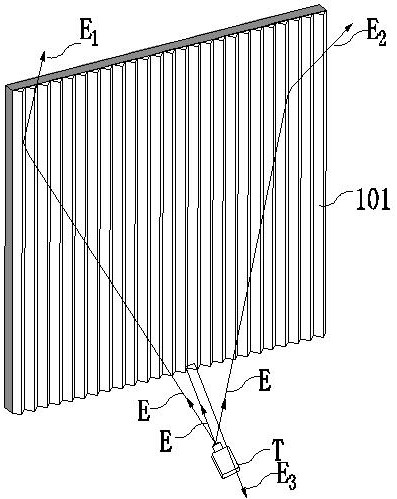
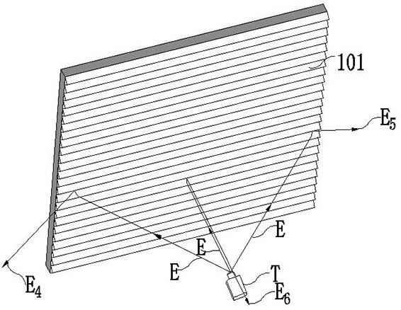
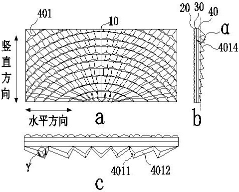
[0061] Such as image 3 as shown, image 3 a is a front view of the optical projection screen 10, image 3 b is a side view of the optical projection screen 10, image 3 c is a top view of the optical projection screen 10 . An optical projection screen 10 includes a surface layer 20, an imaging layer 30, and a reflective layer 40 arranged in sequence from the viewer's direction, and the reflective layer 40 includes an optical microstructure layer. Several optical microstructure blocks 401 arranged are formed along a concentric arc array, and each optical microstructure block 401 includes two main reflection surfaces, which are respectively a first main reflection surface 4011 and a second main reflection surface 4012, and the first main reflection surface The intersection line 4014 of 4011 and the second main reflection surface 4012 in space has a projection on the plane 50 parallel to the screen surface of the optical projection screen 10 and is perpendicular to the vertic...

Embodiment 2

[0077] Based on the first embodiment, it is determined that the optical microstructure block 401 includes three reflective surfaces. Such as Figure 20 are three views of the optical projection screen 10, wherein Figure 20 a is a front view of the optical projection screen 10, Figure 20 b is a side view of the optical projection screen 10, Figure 20 c is a top view of the optical projection screen 10 . An optical projection screen 10, comprising a surface layer 20, an imaging layer 30, and a reflective layer 40 arranged in sequence from the viewer's direction, the reflective layer 40 comprising an optical microstructure layer, and the optical microstructure layer is arranged in sequence along the vertical direction of the optical projection screen Several optical microstructure blocks 401 are formed in an array in the horizontal direction of the optical projection screen; each optical microstructure block 401 includes three reflective surfaces, which are respectively the...

Embodiment 3

[0079] Such as Figure 22 are three views of the optical projection screen 10, wherein Figure 22 a is a front view of the optical projection screen 10, Figure 22 b is a side view of the optical projection screen 10, Figure 22 c is a top view of the optical projection screen 10 . An optical projection screen 10 includes a surface layer 20, an imaging layer 30, and a reflective layer 40 arranged in sequence along the viewer's direction. The reflective layer includes an optical microstructure layer. The microstructure block 401 is formed along an elliptical arc array whose center is at the same point. The optical microstructure block 401 includes two main reflection surfaces, which are respectively a first main reflection surface 4011 and a second main reflection surface 4012. The first main reflection surface 4011 The intersection line 4014 with the second main reflecting surface 4012 in space has an included angle β with the curtain plane 50 of the optical projection screen...


PUM


Abstract

An optical projection screen and a projection system belong to the field of optical projection technology. The optical projection screen includes a surface layer, an imaging layer, and a reflection layer arranged in sequence along the direction of the viewer. The reflection layer includes an optical microstructure layer. A number of optical microstructure blocks arranged in sequence in the vertical direction of the projection screen are formed along a concentric arc array or a number of optical microstructure blocks arranged in sequence in the horizontal direction of the optical projection screen are formed along an elliptical arc array with the center at the same point; the optical microstructure block It includes two main reflective surfaces, and the intersecting line of the main reflective surfaces in space has an included angle with the curtain plane of the optical projection screen. The present invention adjusts the reflection of the projected light toward the viewer by controlling the angle between the optical microstructure block and the screen plane, significantly reduces the loss of the projected light emitted by the optical projection screen to the projector, improves the utilization rate of light energy, and makes the optical projection screen and projection The system has extremely high brightness gain and brightness uniformity.

Description

technical field [0001] The invention belongs to the technical field of optical projection, and relates to an optical projection screen and a projection system, in particular to an optical projection screen and a projection system with high brightness gain and high brightness uniformity. Background technique [0002] In recent years, with the development of projection display technology, projection TVs with projectors and optical projection screens have been favored by more and more consumers due to their excellent performance such as wide color gamut, true colors, and healthy eye protection. Generally speaking, the projector in a projection TV has a decisive impact on the performance of the entire projection TV system such as color gamut, color, and brightness. The problem of heavy weight has become a pain point that consumers generally pay attention to. Therefore, it has become the common goal of all major manufacturers to make the projection size small, easy to install, r...

Claims


Application Information

Patent Timeline
Patent Type & Authority Patents(China)
IPC IPC(8): G03B21/56G03B21/60
CPCG03B21/56G03B21/60
Inventor 张益民胡世加陈智超
Owner CHENGDU FSCREEN SCI TECH
Why Eureka
Try Eureka