Self-generating delay LED lamp for smart home

A technology of smart home and LED lights, which is applied in the direction of electric light source, circuit layout, with built-in power supply, etc. It can solve the problems of inconvenient use of time-delayed LED lights, and achieve the effects of improving brightness, improving safety, and avoiding electric shock

Inactive Publication Date: 2020-10-13
方玉玲
View PDF6 Cites 0 Cited by
  • Summary
  • Abstract
  • Description
  • Claims
  • Application Information

AI Technical Summary

Problems solved by technology

[0005] The purpose of the present invention is to solve the problem of inconvenient use of most traditional time-delay LED lights, and to provide a self-generating time-delay LED light for smart homes that is more convenient to use

Method used


Image

  • Self-generating delay LED lamp for smart home
  • Self-generating delay LED lamp for smart home
  • Self-generating delay LED lamp for smart home

Examples


Embodiment 1

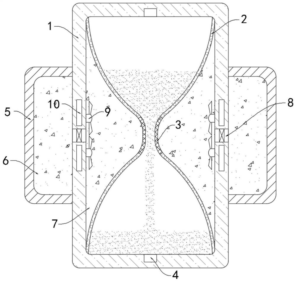
[0025] like Figure 1-2 As shown, a self-generating time-delay LED lamp for smart homes includes a transparent and rigid frame 1. It should be noted that the frame 1 has insulation properties, which can effectively prevent the internal current from leaking out, thereby causing power loss. Loss and affect the brightness of the whole device, can also avoid the use of personnel electric shock, the inner top surface and the inner bottom surface of the frame body 1 are fixedly connected with a symmetrically arranged funnel-shaped transparent lampshade 2 (such as figure 1 shown), each transparent lampshade 2 is fixedly embedded with an LED light bar (not shown in the figure).

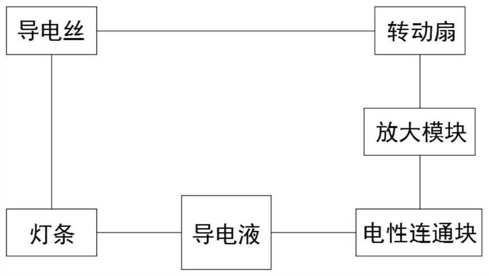
[0026] The two transparent lampshades 2 are connected through the elastic tube 3 with the conductive wire embedded inside. One end of the conductive wire in the elastic tube 3 is exposed in the tube of the elastic tube 3. The transparent lampshade 2 contains a conductive liquid, which can be Liquid water, th...

Embodiment 2

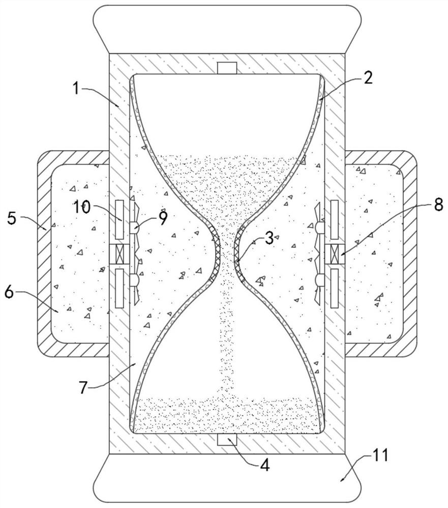
[0036] like image 3 As shown, the difference between the present embodiment and the first embodiment is that the upper and lower ends of the frame body 1 are fixedly connected with a counterweight platform 11 .

[0037] In this embodiment, when the frame body 1 is turned over, the conductive liquid will be in the transparent lampshade 2 at the upper end. At this time, the entire frame body 1 is top-heavy and prone to tipping over. Well, the toppling of the frame body 1 can be effectively prevented.


PUM


Abstract

The invention belongs to the field of smart home, and particularly relates to a self-generating delay LED lamp for smart home. The LED lamp comprises a transparent hard frame body, funnel-shaped transparent lampshades which are symmetrically arranged are fixedly connected to the inner top surface and the inner bottom surface of the frame body, an LED light bar is fixedly embedded in each transparent lampshade, the two transparent lampshades are communicated through an elastic tube in which a conductive wire is embedded, conductive liquid is contained in the transparent lampshades, and the conductive wire in the elastic tube is electrically connected with the LED light bars. When the device needs to be used, only the whole frame body needs to be inversely buckled to enable the conductive liquid to flow into the transparent lampshade below from the transparent lampshade at the upper end, the liquid column of the conductive liquid enables an electric communication block to be communicatedwith the conductive wire in the elastic tube, so that the conduction of the whole internal circuit can be realized, the LED light bars are lighted up by gently pinching an elastic deformation layer to generate a current, and the LED light bars are extinguished when the conductive liquid in the transparent lampshade at the upper end is used up. The LED lamp is convenient to use, and is convenientto operate in a dark environment.

Description

technical field [0001] The invention belongs to the field of smart home, and in particular relates to a self-generating time-delay LED lamp for smart home. Background technique [0002] With the continuous improvement of living standards, smart homes are becoming more and more popular. Time-delay LED lights are among the more common smart home appliances, which provide greater convenience for life. Most of the existing time-delay LED lights are divided by resistors. Voltage way to power the control circuit. [0003] Most of the traditional time-delay LED lights are fixed on the wall, and you often need to find the corresponding button to turn them on at night, which is inconvenient to use, and most of the traditional time-delay LED lights extend the lighting time in It is set during production, and it is difficult to adjust during use. It is easy to cause the lighting time of the lamp body to be too long or too short. If it is too long, it will waste more power, and if it i...

Claims


Application Information

Patent Timeline
Patent Type & Authority Applications(China)
IPC IPC(8): F21S9/04F21V23/02F21V21/00F21Y115/10
CPCF21S9/04F21V21/00F21V23/02F21Y2115/10
Inventor 方玉玲于小辉
Owner 方玉玲
Why Eureka
Try Eureka