Anti-clogging rainwater grate for municipal roads

A rainwater grate, municipal road technology, applied in water supply installations, waterway systems, drainage structures, etc., can solve problems such as water inlets being easily blocked by impurities, pedestrians and vehicles traveling, and people's quality of life being reduced. Practicality, the effect of improving the range of activities

Active Publication Date: 2021-09-07
宁波齐兴建设有限公司
View PDF0 Cites 0 Cited by
  • Summary
  • Abstract
  • Description
  • Claims
  • Application Information

AI Technical Summary

Problems solved by technology

[0003] In the prior art, the drainage structure of the rainwater grate is relatively simple, and the water inlet is easily blocked by impurities during use. Especially in the face of heavy rain, it is easy to accumulate rainwater on the ground, which will affect the movement of pedestrians and vehicles and reduce the people's quality of life

Method used


Image

  • Anti-clogging rainwater grate for municipal roads
  • Anti-clogging rainwater grate for municipal roads
  • Anti-clogging rainwater grate for municipal roads

Examples


Embodiment 1

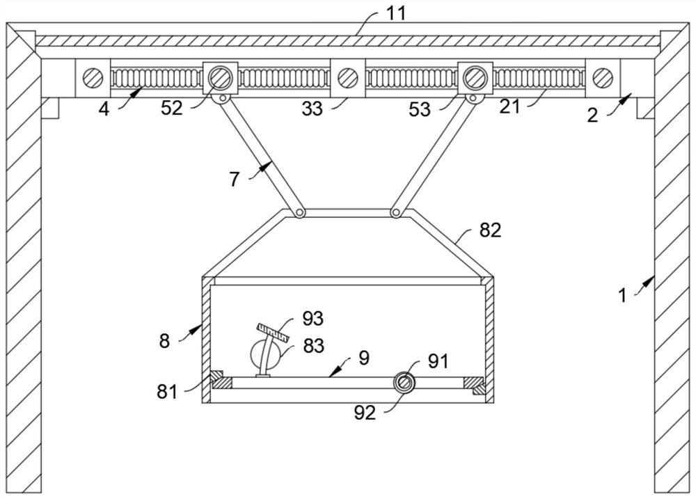
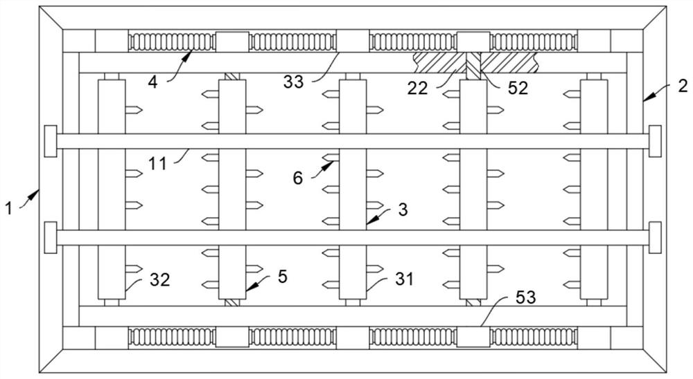
[0028] Such as Figure 1-2 As shown, a kind of anti-clogging rainwater grate for municipal roads comprises a support frame 1, and the support frame 1 is detachably connected with a cover plate 2. The staff works on the placement of the device.

[0029] The cover plate 2 is provided with a fixed rod 3, and a movable rod 5 is movably connected between adjacent fixed rods 3 through a spring tube 4. It should be noted that the fixed rod 3 includes a main rod 31 and a side rod 32, and the movable rod 5 is movably connected to the The position between the main rod 31 and the side rod 32.

[0030] The specific movable connection process: the cover plate 2 is symmetrically provided with a guide rail 21, the guide rail 21 is provided with a rack 22, and both sides of the moving rod 5 close to the rack 22 are provided with a tooth column 52, through the meshing of the tooth column 52 and the rack 22 , so that the moving rod 5 forms a rotating work during the moving process, which faci...

Embodiment 2

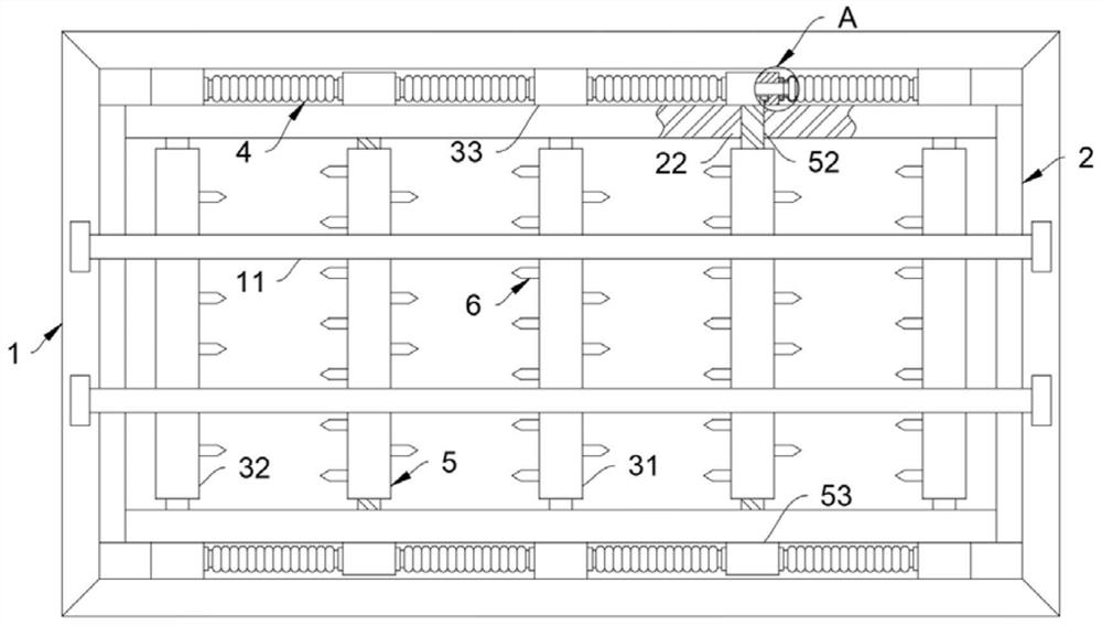
[0041] Such as Figure 3-6 Shown, the difference between this embodiment and embodiment 1 is:

[0042] The fixed rod 3 and the moving rod 5 are all provided with a ventilation layer 51, one end of the ventilation layer 51 communicates with the spring tube 4, the cutting blade 6 is provided with an air outlet 61, and the other end of the ventilation layer 51 communicates with the air outlet 61, and the air outlet 61 is symmetrically arranged on the rotating side of the cutting blade 6 .

[0043] Specifically, the spring tube 4 adopted in this embodiment is a fully sealed spring tube, the main rod 31 of the fixed rod 3 is provided with a double ventilation layer 51, which is used for the intake and exhaust of the spring tube 4 on both sides, and the cutting blade 6 The air outlet holes 61 are arranged symmetrically at the tip of the knife, and the air outlet holes 61 are arranged obliquely so that the cutting blade 6 can blow the airflow to both sides when cutting, so as to imp...


PUM


Abstract

The invention belongs to the field of municipal facilities, in particular to an anti-clogging rainwater grate for municipal roads, comprising a support frame, wherein a cover plate is detachably connected to the support frame, and the cover plate is provided with a fixing rod, adjacent to the fixing rod A moving rod is movably connected between them through a spring tube, the fixed rod and the moving rod are both provided with cutting blades, the moving rod is rotatably connected with a water collection tank through a guide rod, and the end of the water collection tank away from the cover plate is rotated and connected with a bottom plate . The invention effectively avoids the water inlet of the grate from being blocked by impurities when working in rainy weather by setting an anti-clogging rainwater grate for municipal roads, improves the drainage efficiency of rainwater, and ensures the normal operation of traffic order.

Description

technical field [0001] The invention belongs to the field of municipal facilities, in particular to an anti-clogging rainwater grate for municipal roads. Background technique [0002] The rainwater grate is welded by flat steel and twisted square steel or flat steel and flat steel. The rainwater grate has the advantages of beautiful appearance, optimal drainage, high strength, many specifications and low cost, so the steel grating rainwater grate is usually used. With the continuous increase of municipal construction requirements for road drainage, some deficiencies in the actual use of rainwater grates urgently need to be improved. [0003] In the prior art, the drainage structure of the rainwater grate is relatively simple, and the water inlet is easily blocked by impurities during use. Especially in the face of heavy rain, it is easy to accumulate rainwater on the ground, which will affect the movement of pedestrians and vehicles and reduce the people's quality of life....

Claims


Application Information

Patent Timeline
Patent Type & Authority Patents(China)
IPC IPC(8): E03F5/06E03F5/10E03F7/00E03F5/14B26D1/28B26D7/08
CPCB26D1/28B26D7/088E03F5/06E03F5/10E03F5/14E03F7/00
Inventor 宋苏明汪群英唐姗姗
Owner 宁波齐兴建设有限公司
Why Eureka
Try Eureka