Signal transmitting and receiving device, electronic device and equipment

A signal and signal source technology, which is applied in the field of electronic devices and equipment, and signal sending and receiving devices, can solve the problems of time-consuming and high cost of sending and receiving machine detection, and achieve the effect of reducing self-inspection cost and rapid self-inspection

Active Publication Date: 2020-11-13
CALTERAH SEMICON TECH SHANGHAI CO LTD
View PDF9 Cites 1 Cited by
  • Summary
  • Abstract
  • Description
  • Claims
  • Application Information

AI Technical Summary

Problems solved by technology

[0005] However, the detection cost of the above-mentioned transceiver is high and time-consuming

Method used


Image

  • Signal transmitting and receiving device, electronic device and equipment
  • Signal transmitting and receiving device, electronic device and equipment
  • Signal transmitting and receiving device, electronic device and equipment

Examples


Embodiment 1

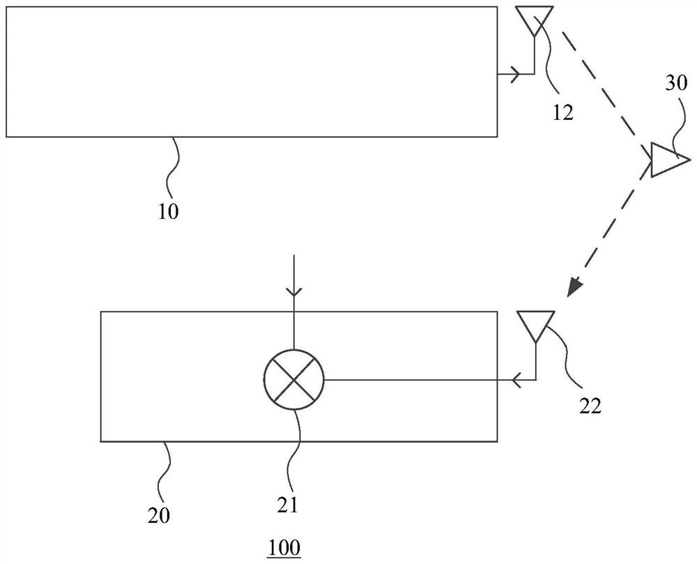
[0099] Figure 1 The structural diagram of the signal transmitting and receiving device provided for embodiment 1 of the present application Figure I 。 See Figure 1 As shown, the signal transmitting and receiving device 100 provided by the embodiment of the application has an operating state and a self-test state. The signal transmitting and receiving device 100 includes at least one transmitting channel 10 and at least one receiving channel 20, that is, the number of transmitting channels 10 and receiving channels 20 can be flexibly set according to the actual demand. This may not be limited in the embodiment of the present application. Here is Figure 1 The signal transmitting and receiving device 100 including a transmitting channel 10 and a receiving channel 20 is schematically described as an example.

[0100] Wherein, the transmission channel 10 is used for transmitting the first signal; A receiving channel 20 for receiving a second signal; The second signal is an echo signal...

Embodiment 2

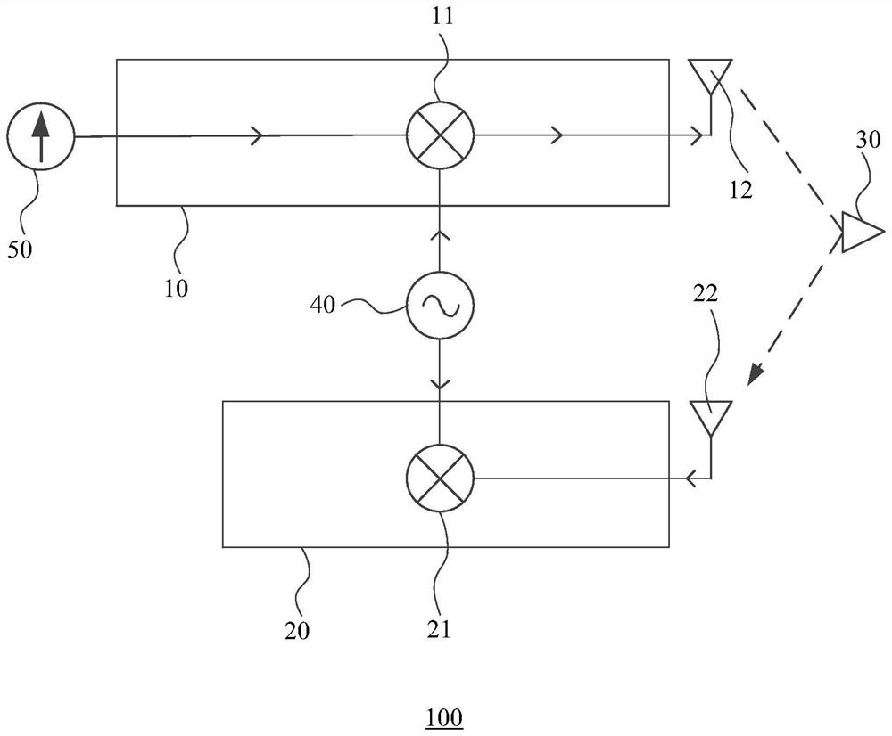
[0128] Figure 4 The structural diagram of the signal transmitting and receiving device provided for embodiment 2 of the present application. See Figure 4 The embodiment of the present application provides a signal transmitting and receiving device 100, which comprises at least one transmitting and receiving channel 70, and the transmitting and receiving channel 70 comprises a transmitting channel 10 and a receiving channel 20; as well as

[0129] The receiving channel 20 includes a first mixer 21 for down converting the echo signal received by the receiving channel 20 based on the reference signal; Wherein, when the signal transmitting and receiving device 100 is in the working state, the frequency of the signal transmitted by the transmission channel is the same as that of the reference signal; as well as

[0130] When the signal transmitting and receiving device 100 is in the self-test state, the frequency of the signal transmitted by the transmission channel is different from ...

Embodiment 3

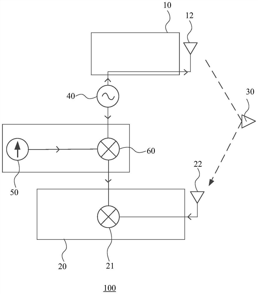
[0141] Figure 5 The structural diagram of the signal transmitting and receiving device provided for embodiment 3 of the present application Figure I 。 See Figure 5 As shown, the present embodiment provides a signal transmitting and receiving device 100, which has an operating state and a self-test state. The signal transmitting and receiving device 100 includes:

[0142] A local oscillator signal source 80 for providing a local oscillator signal;

[0143] The transmitting antenna 12 is connected with the local oscillator signal source 80, and the transmitting antenna 12 is used to transmit the first signal formed based on the local oscillator signal;

[0144] A receiving antenna 22 for receiving a second signal; The second signal is an echo signal formed based on the first signal;

[0145] The first mixer 21 is connected with the receiving antenna 22 and the local oscillator signal source 80 respectively; as well as

[0146] The first mixer 21 is used for down converting the seco...


PUM


Abstract

The invention provides a signal transmitting and receiving device, an electronic device and equipment. The signal transmitting and receiving device comprises at least one transmitting channel which isused for transmitting a first signal and at least one receiving channel which is used for receiving a second signal, wherein the second signal is an echo signal formed based on the first signal. Thereceiving channel comprises a first frequency mixer, and the first frequency mixer is used for performing down-conversion on the second signal based on the reference signal; when the signal transmitting and receiving device is in a working state, the frequency of the first signal is the same as that of the reference signal; when the signal transmitting and receiving device is in a self-checking state, the frequency of the first signal is different from the frequency of the reference signal. The invention provides a signal transmitting and receiving device, which can reduce the self-checking cost of a transmitting and receiving machine and save the self-checking time.

Description

[0001] The invention is required to be submitted to the China Patent Office on February 28, 2020, with application number 202010131001.5 and application name "transceiver"; Submitted to the China Patent Office on February 28, 2020, with application No. 202010131614.9 and application name of "detection device and method of transceiver"; And the priority of the Chinese patent application with the application number of 202010131029.9 submitted to the China Patent Office on February 28, 2020 and the application name of "radar transceiver machine control method and system", which is combined with the whole content of this application by reference. technical field [0002] The invention relates to the technical field of electronic circuits, in particular to a signal transmitting and receiving device, an electronic device and a device. Background technology [0003] Transceiver is an important component in communication and sensor system. It is mainly used for signal transmission and rec...

Claims


Application Information

Patent Timeline
Patent Type & Authority Applications(China)
IPC IPC(8): H04B17/10H04B17/20
CPCH04B17/10H04B17/20
Inventor 刘正东
Owner CALTERAH SEMICON TECH SHANGHAI CO LTD
Why Eureka
Try Eureka