Dodging rod fixing device

A technology of fixing devices and dodging rods, which is applied in the field of exposure and projection, can solve problems such as the inability to ensure the stability of the center of the light-incoming surface and the light-emitting surface, loss of light energy, and damage to the dodging rod, so as to improve the dodging effect, The effect of sufficient area and reduced light energy loss

Active Publication Date: 2020-12-04
源能智创(江苏)半导体有限公司
View PDF7 Cites 0 Cited by
  • Summary
  • Abstract
  • Description
  • Claims
  • Application Information

AI Technical Summary

Problems solved by technology

[0004] There are two main installation methods at present. One is that the dodging rod is directly in rigid contact with the fixing device. In order to ensure its center alignment, the contact area between the dodging rod and the fixing device is relatively large, and its side cannot be contacted as much as possible. Into the air, resulting in poor uniformity, large area of ​​rigid contact is also prone to greater stress caused by temperature and damage to the uniform rod; the other method mainly uses a long soft support, long-term laser irradiation will accelerate With the aging of the soft support, the fixing effect is greatly weakened, and the center of the light-incoming surface and the light-emitting surface cannot be guaranteed to remain stable. If the center position deviates greatly, it will cause a large loss of light energy

Method used


Image

  • Dodging rod fixing device
  • Dodging rod fixing device
  • Dodging rod fixing device

Examples


Embodiment Construction

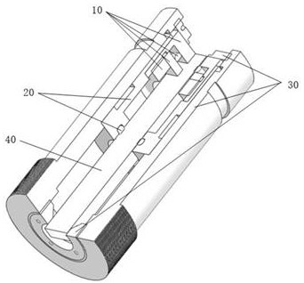
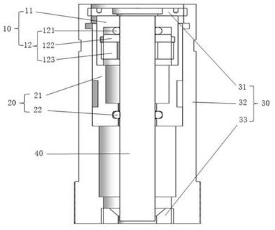
[0029] In order to make the technical solution of the present invention more clear, the embodiments of the present invention will be described below in conjunction with the accompanying drawings. It should be understood that the specific descriptions of the embodiments are only used to teach those skilled in the art how to implement the present invention, rather than exhaustively listing all possible ways of the present invention, and not limiting the specific implementation scope of the present invention. Based on the embodiments of the present invention, all other embodiments obtained by persons of ordinary skill in the art without making creative efforts shall fall within the protection scope of the present invention.

[0030] In describing the present invention, it is to be understood that the terms "center", "upper", "lower", "front", "rear", "left", "right", "vertical", "horizontal", The orientations or positional relationships indicated by "top", "bottom", "inner", "out...


PUM


Abstract

A dodging rod fixing device comprises a fixing assembly and an adjusting and supporting assembly. The fixing assembly is used for directly fixing a dodging rod and comprises a base body and a first fastening assembly, a fastening counter bore is formed in one end of the base body, a rectangular light-in positioning through hole leading to the fastening counter bore is formed in the other end of the base body, the dodging rod is arranged in the base body from the rectangular light-in positioning through hole and penetrates through the fastening counter bore, and the first fastening assembly isinstalled in the fastening counter bore so as to fix the dodging rod. The adjusting and supporting assembly is used for supporting and fixing the fixing assembly and comprises a supporting base body and a second fastening assembly, a supporting and positioning stepped hole is formed in the supporting base body and comprises a supporting stepped hole body and a light emitting positioning through hole, and the base body is arranged in the supporting stepped hole body; the light emitting surface of the dodging rod is located in the light emitting positioning through hole or penetrates through thelight emitting positioning through hole, and the second fastening assembly compresses the base body. The dodging rod fixing device has the beneficial effects that the dodging rod can be in full contact with air, and the center of the dodging rod is prevented from deviating.

Description

technical field [0001] The invention belongs to the technical field of exposure and projection, and in particular relates to a uniform light rod fixing device. Background technique [0002] In exposure and projection technology, the outgoing light generated by the light source is generally not uniform enough to meet the requirements of high-quality imaging. Therefore, a dodging rod is usually added on the propagation path of the outgoing light of the light source to dodge it, and then enter the subsequent optical elements. The uniform light treatment mainly uses the principle of total reflection of light. The light is reflected multiple times in the uniform light rod to form a two-dimensional virtual light source matrix, so that the light passing through it can achieve a uniform effect at the exit. [0003] In practical applications, the dodging rod is mostly a rectangular parallelepiped glass device, which is small in size and easily broken. The installation and fixing met...

Claims


Application Information

Patent Timeline
Patent Type & Authority Applications(China)
IPC IPC(8): G02B7/00
CPCG02B7/00
Inventor 章卫平张柯李伟成张雷
Owner 源能智创(江苏)半导体有限公司
Why Eureka
Try Eureka