Millimeter-wave radar and camera rapid joint calibration method

A millimeter-wave radar and joint calibration technology, applied in image analysis, image data processing, radio wave measurement systems, etc., can solve the problems of reduced calibration accuracy, poor reflection intensity, irregular shape, etc., to improve joint calibration speed, reflection strong effect

Pending Publication Date: 2020-12-11
北京中科原动力科技有限公司
View PDF0 Cites 8 Cited by
  • Summary
  • Abstract
  • Description
  • Claims
  • Application Information

AI Technical Summary

Problems solved by technology

[0008] The present invention is to solve the problem that existing millimeter-wave radar and camera joint calibration methods in the prior art have strong preconditions, and complex operations are often required to meet the required preconditions; some select targets with large and irregular shapes. The reference object leads to the inaccurate horizontal position of the calibration, which causes the problem of the decre

Method used


Image

  • Millimeter-wave radar and camera rapid joint calibration method
  • Millimeter-wave radar and camera rapid joint calibration method
  • Millimeter-wave radar and camera rapid joint calibration method

Examples


Embodiment 1

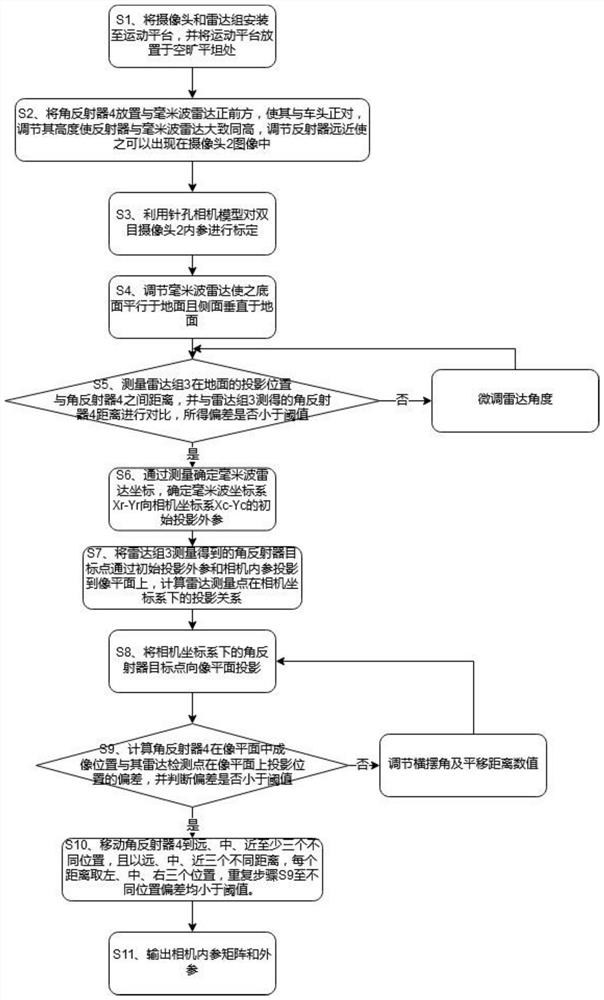
[0050] Such as figure 1 As shown, a rapid joint calibration method of millimeter-wave radar and camera 2 includes the following steps:

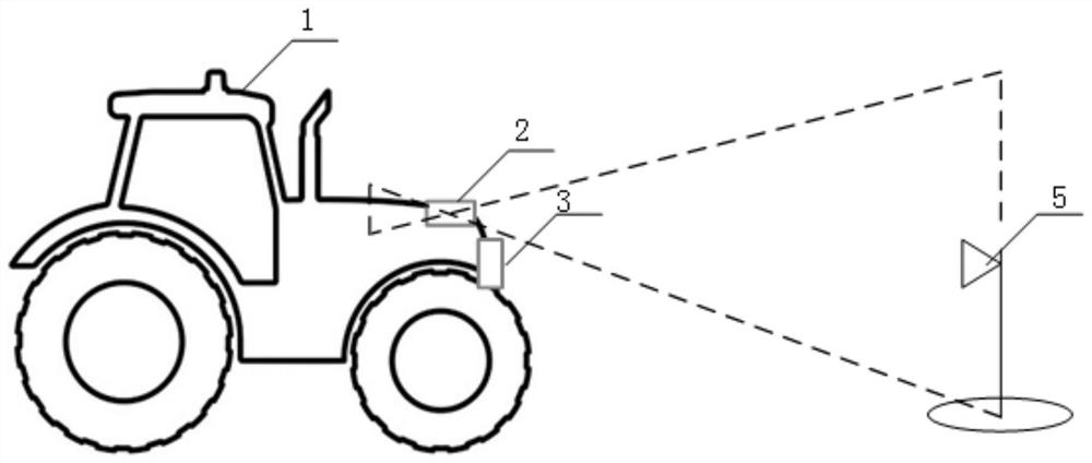
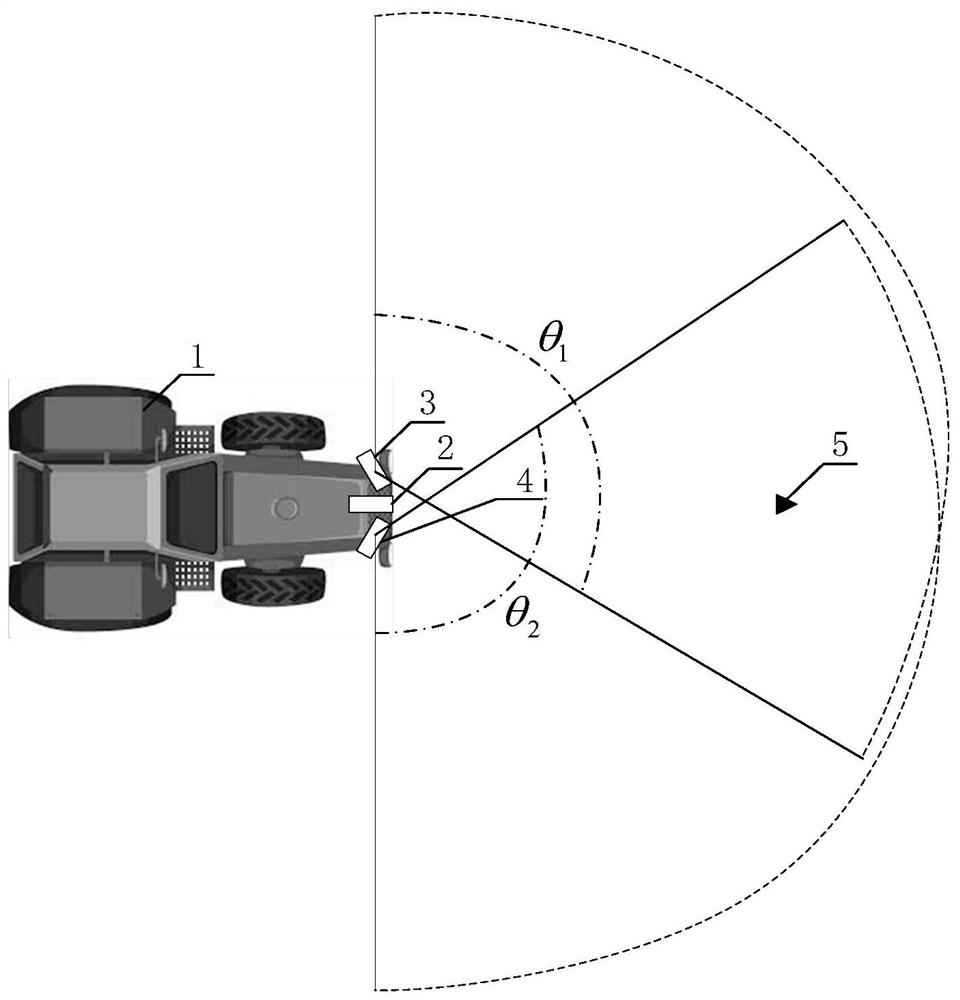
[0051] S1. Install the millimeter-wave radar and camera 2 to the fixed position of the motion platform 1, that is, the position of the front of the vehicle, and place the motion platform 1 in an open and flat place, which can be an outdoor square or an indoor flat hall;

[0052] S2. Place the corner reflector 4 directly in front of the millimeter-wave radar so that it faces the front of the vehicle, adjust its height so that the reflector is roughly the same height as the millimeter-wave radar, and adjust the distance of the reflector so that it can appear in the image of the camera 2;

[0053] S3. Use the pinhole camera model to calibrate the internal parameters of the binocular camera 2. In general applications, the measurement data of the millimeter-wave radar only needs to be projected onto one image plane. In this embodiment, the left ob...


PUM


Abstract

The invention relates to a millimeter-wave radar and camera rapid joint calibration method, and the method comprises the following steps: S1, enabling a camera and a radar group to be installed on a motion platform, and enabling the motion platform to be placed at an open flat place; s2, arranging a corner reflector right in front of the motion platform, adjusting the height of the corner reflector to be the same as the height of the radar set, and adjusting the distance between the corner reflector and the radar set until the corner reflector appears in the image range of the camera; s3, calibrating the internal parameters of the camera by using the pinhole camera model and adjusting the radar angle at the same time; s4, determining an initial projection external parameter of the millimeter wave coordinate system Xr-Yr to the camera coordinate system Xc-Yc; s5, adjusting a yaw angle and a translation distance value in the external parameter by calculating the deviation between the imaging position of the corner reflector in the image plane and the projection position of the radar detection point on the image plane; s6, outputting an internal parameter matrix and an external parameter of the camera, and completing the calibration. The corner reflector is high in reflection intensity and small in size, and better feedback can be obtained.

Description

technical field [0001] The invention relates to the technical field of multi-sensor joint calibration, in particular to a rapid joint calibration method for a millimeter-wave radar and a camera. Background technique [0002] For unmanned motion platforms, whether it is an intelligent driving vehicle on a regular road, an unmanned agricultural machine on an unstructured road, or a mobile robot in an indoor scene, multi-sensor fusion is used to accurately perceive and identify the target and improve its environment. Cognitive abilities are very important. The use of multi-sensor fusion can effectively avoid accidents caused by the failure of a single sensor, and the complementary advantages of multiple sensors can significantly improve the perception accuracy of the perception system. Among different sensor fusion schemes, the camera has become an indispensable part of the perception system of the unmanned motion platform due to its cheap price and the ability to provide rich...

Claims


Application Information

Patent Timeline
IPC IPC(8): G06T7/80G01S7/40G01C25/00
CPCG01C25/00G01S7/4052G06T7/80G01S7/4095
Inventor 杨顺韩威郑思仪袁野刘继凯国大伟刘凯史志坚
Owner 北京中科原动力科技有限公司
Why Eureka
Try Eureka