Manipulator automatic dispensing mechanism

A technology of automatic glue dispensing and manipulator, which is applied in the direction of manipulator, smoke and dust removal, chemical instruments and methods, etc. It can solve the problems of inconvenient application and control adjustment, peculiar smell cannot be removed in real time, and affect the air quality of the working environment, etc.

Active Publication Date: 2021-02-12
江西立讯智造有限公司
View PDF5 Cites 2 Cited by
  • Summary
  • Abstract
  • Description
  • Claims
  • Application Information

AI Technical Summary

Problems solved by technology

[0004] The existing robot automatic dispensing mechanism is inconvenient for application and control adjustment, and the odor generated by dispensing cannot be removed in real time, which affects the air quality of the working environment, and needs to be improved to overcome the shortcomings in current practical applications

Method used


Image

  • Manipulator automatic dispensing mechanism
  • Manipulator automatic dispensing mechanism
  • Manipulator automatic dispensing mechanism

Examples


Embodiment 1

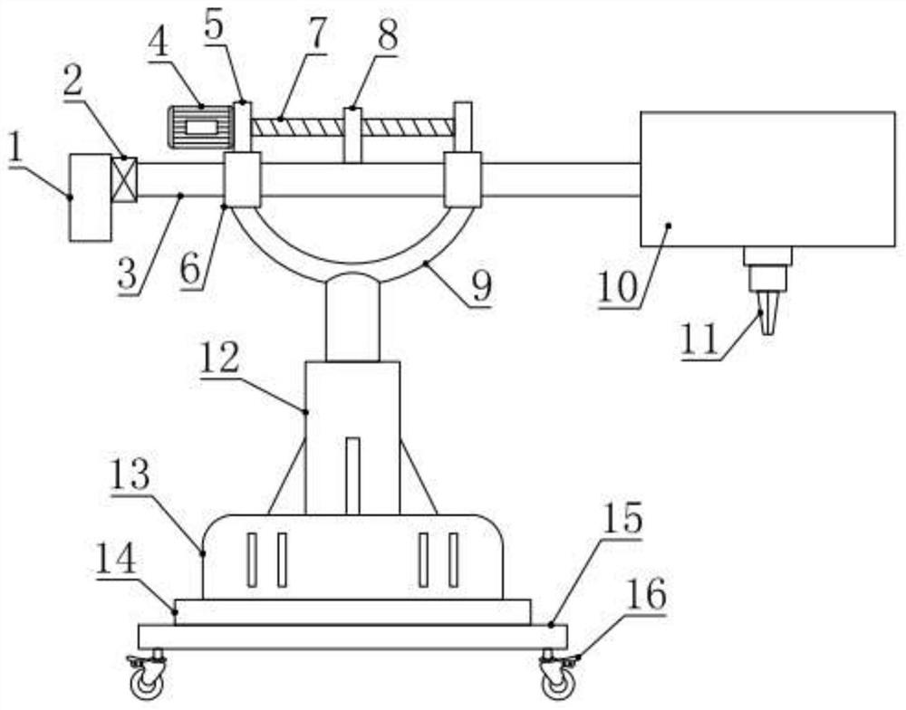
[0025] see figure 1 , in the embodiment of the present invention, an automatic dispensing mechanism of a manipulator includes a base plate base 15, a support base 14 is installed and fixed on the base base base 15, a rotary table 13 is installed on the support base 14, and the rotary table 13 can relatively support Seat 14 rotates, and the specific rotation driving structure of turntable 13 adopts the prior art and is not specifically limited; the first telescopic cylinder 12 is installed and fixed on the turntable 13, and a U-shaped cylinder is fixed on the upper end of the first telescopic cylinder 12. Bracket 9, the two ends of U-shaped brace 9 are respectively installed and fixed with a support sleeve 6, cooperate and slide in two support sleeves 6 and be provided with horizontal tube 3, also be installed on two described support sleeves 6 The drive assembly that drives the horizontal tube 3 to move along the support sleeve 6, a dispensing box 10 is installed at one end of...

Embodiment 2

[0028] see Figure 1-4 , the difference between this embodiment and embodiment 1 is:

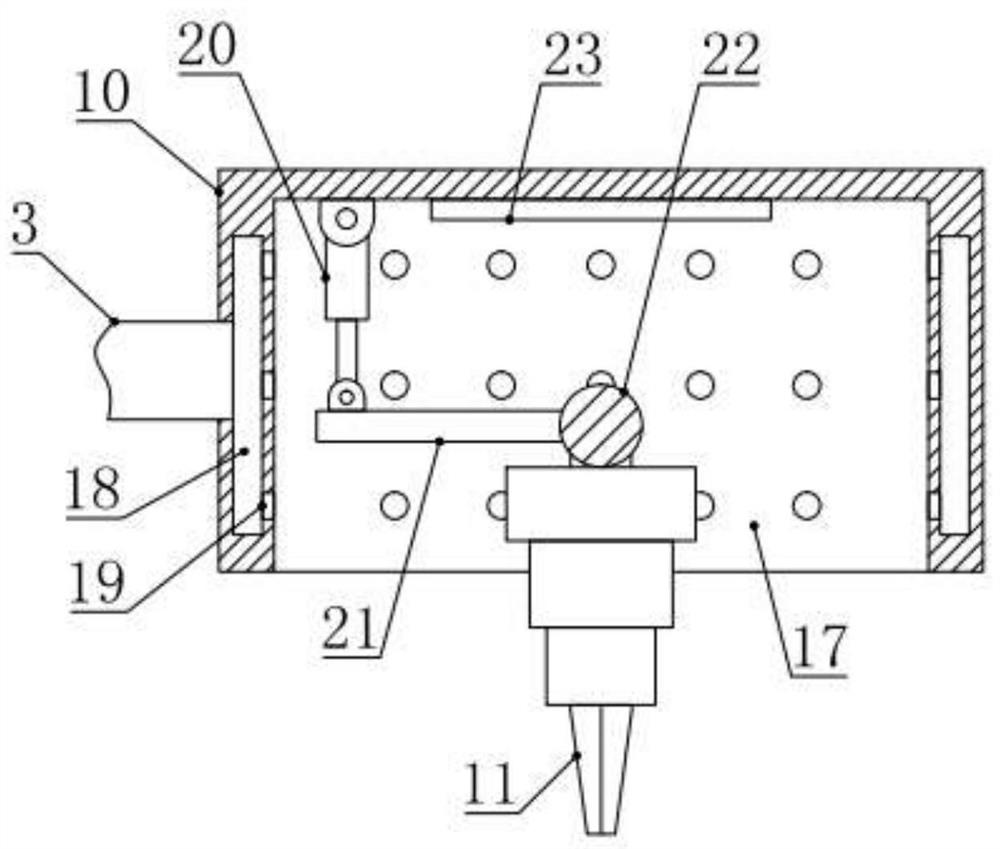
[0029] In this example, if figure 2 with 3 As shown, the dispensing box 10 is provided with an installation cavity 17 with a lower opening, and the outside of the installation cavity 17 is also provided with an annular cavity 18 in the side wall of the dispensing box 10, and one end of the horizontal tube 3 communicates with the annular cavity 18, The inner side of the annular cavity 18 is also provided with some exhaust holes 19 communicated with the installation cavity 17, through the work of the exhaust fan 2, because the horizontal pipe 3 is communicated with the exhaust holes 19 through the annular cavity 18, a negative air flow can be generated at the exhaust holes 19. The pressure can suck the peculiar smell; further, a lighting lamp 23 is also installed on the top of the installation cavity 17, and the lighting lamp 23 is used for auxiliary lighting to improve the quality of dispe...


PUM


Abstract

The invention relates to the technical field of dispensing, in particular to a mechanical arm automatic dispensing mechanism. The mechanical arm automatic dispensing mechanism comprises a bottom platebase, a supporting base is fixedly installed on the bottom plate base, a rotating table is installed on the supporting base, a first telescopic cylinder is fixedly installed on the rotating table, aU-shaped supporting frame is fixedly installed at the upper end of the first telescopic cylinder, the two ends of the U-shaped supporting frame are each fixedly provided with a supporting sleeve, a transverse pipes is arranged in the two supporting sleeves in a matched and sliding mode, driving assemblies used for driving the transverse pipes to move along the supporting sleeves are further installed on the two supporting sleeves, a dispensing box is installed at one end of the transverse pipe, a dispensing head is installed in the dispensing box through a swing assembly, an exhaust fan used for conducting negative pressure suction on an inner cavity of the dispensing box through the inner cavity of the transverse pipe is installed at the other end of the transverse pipe, and an air filtering device is installed on an air outlet of the exhaust fan. It is convenient to apply, control and adjust the dispensing mechanism, peculiar smells generated during dispensing can be removed in realtime, and the air quality of the working environment is improved.

Description

technical field [0001] The invention relates to the field of dispensing technology, in particular to an automatic dispensing mechanism of a manipulator. Background technique [0002] Glue dispensing is a process, also known as sizing, gluing, glue pouring, glue dropping, etc. It is to smear, fill, and drop electronic glue, oil or other liquids on the product, so that the product can stick and fill. , insulation, fixation, smooth surface and so on. [0003] A manipulator is an automatic operating device that can imitate certain movement functions of the human hand and arm to grab, carry objects or operate tools according to a fixed program. The feature is that various expected operations can be completed through programming, and the structure and performance have both the advantages of man and robot. [0004] The existing robotic automatic dispensing mechanism is inconvenient to apply and control, and the odor generated by dispensing cannot be removed in real time, which af...

Claims


Application Information

Patent Timeline
IPC IPC(8): B05C5/02B05C11/10B08B15/04B25J11/00
CPCB05C5/02B05C11/10B08B15/04B25J11/0075
Inventor 郭广涛常红彭迎程增光赵子龙
Owner 江西立讯智造有限公司
Why Eureka
Try Eureka