Wave energy capturing device

A technology for capturing device and wave energy, applied in valve device, valve operation/release device, ocean energy power generation, etc., can solve the problems of difficult water surface control, mixing oil droplets, polluting the environment, etc., to achieve the effect of improving efficiency

Active Publication Date: 2021-02-26
苏州琦谷佳科技有限公司
View PDF9 Cites 1 Cited by
  • Summary
  • Abstract
  • Description
  • Claims
  • Application Information

AI Technical Summary

Problems solved by technology

[0003] When the existing wave energy capture device is used, it only focuses on power generation, without considering the problem of cleaning the water surface at the same time. The garbage on the water surface not only pollutes the environment, but also hinders the operation of the wave energy capture device
The garbage on the water surface is mainly floating garbage and oil. The floating garbage is relatively easy to clean, but the oil is liquid and insoluble in water. There is only a layer of oil on the water surface, which is widely distributed. It is very difficult to collect the oil on the water surface. At the same time, the oil pollution on the water surface It is a mixture of domestic oil and industrial oil, which is difficult to recycle. The commonly used deposition method for oil-water separation requires a stable environment, and concentrated deposition requires a large space. Real-time deposition needs to avoid absorbing too much water and air, too much air Bubbles will be generated during oil deposition, too much water will make it difficult to control the water surface during deposition, rise and fall too fast, making oil deposition on the water surface unstable, easy to mix oil droplets in the water, and carry oil droplets back when the water is discharged In water flow, resulting in insufficient oil cleaning

Method used


Image

  • Wave energy capturing device
  • Wave energy capturing device
  • Wave energy capturing device

Examples


Embodiment Construction

[0034] The following will clearly and completely describe the technical solutions in the embodiments of the present invention with reference to the accompanying drawings in the embodiments of the present invention. Obviously, the described embodiments are only some, not all, embodiments of the present invention. Based on the embodiments of the present invention, all other embodiments obtained by persons of ordinary skill in the art without making creative efforts belong to the protection scope of the present invention.

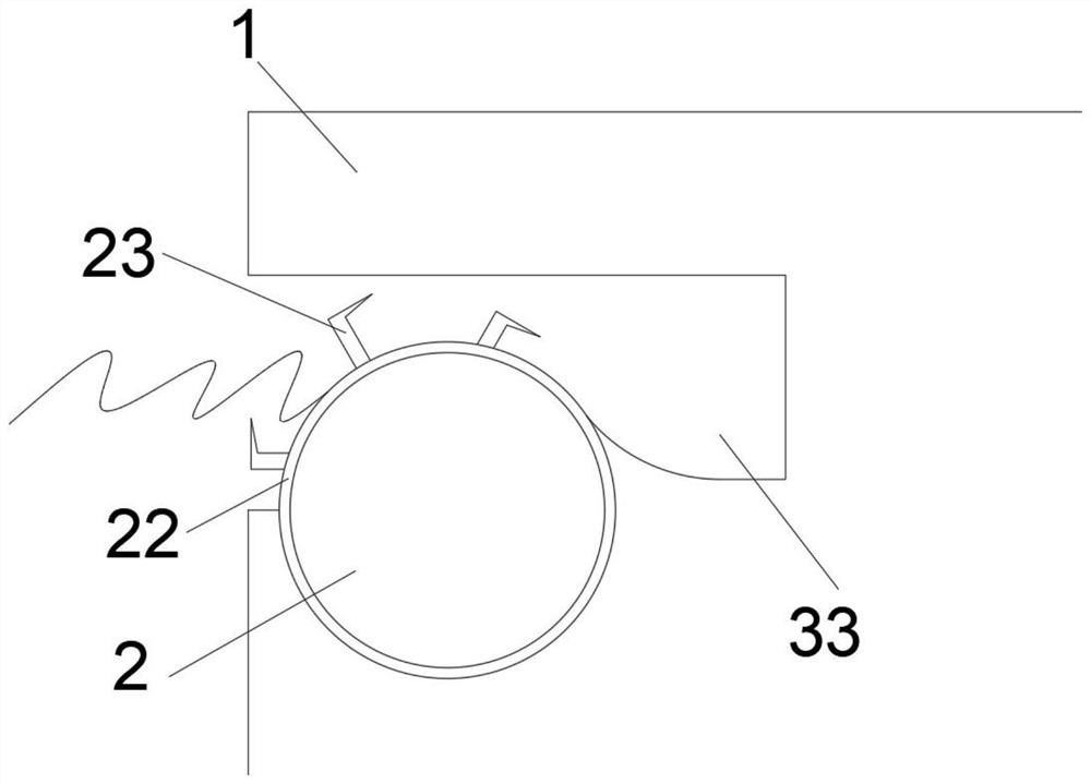
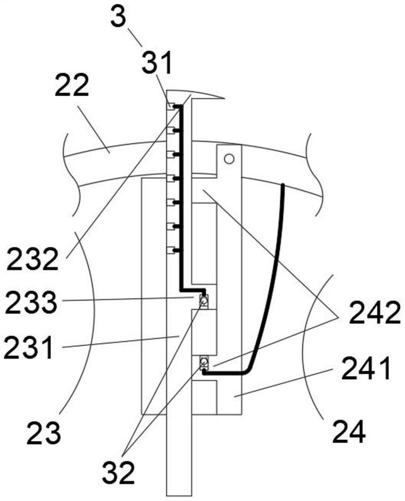
[0035] see Figure 1-11 , the present invention provides a technical solution: as figure 1 , The wave energy capture device includes a fixed platform 1, a capture device 2 is arranged on one side of the fixed platform 1, and the capture device 2 includes a convex rod 21, and a rotating cylinder 22 is arranged on the convex rod 21, and several convex rods are arranged in the middle of the convex rod 21. The vane 23, the oil-water collecting device 3 is arrange...


PUM


Abstract

The invention discloses a wave energy capturing device. The device comprises a fixing table, a capturing device body is arranged at one side of the fixing table, the capturing device body comprises aconvex rod, the convex rod is sleeved with a rotating cylinder, a plurality of blades are arranged in the middle of the convex rod, an oil-water collecting device is arranged in the capturing device body, and a power generation device is arranged at one end of the convex rod. An oil-water separation device is arranged at the other end of the convex rod, the blades and the rotating cylinder form aneccentric wheel structure, so that the blades only extend out of the water surface, waves hit the blades above during impact to drive the rotating cylinder to rotate, and when the rotating cylinder rotates, the oil-water collecting device can be driven to collect oil on the lake surface. The oil-water separation device is used for separating oil water into water, domestic oil and industrial oil,so that the effect of automatically separating and recycling the domestic oil and the industrial oil from the water is achieved, and the wave energy capturing device has the characteristics that the water surface can be cleaned, and the domestic oil and the industrial oil can be separated and recycled.

Description

technical field [0001] The invention relates to the technical field of clean energy, in particular to a wave energy capture device. Background technique [0002] As the world's energy crisis and environmental pollution become more and more serious, new energy sources such as wind power and wave energy are generally favored by countries all over the world. my country clearly proposes to speed up the development of marine resources and promote the upgrading of energy structure. As a clean energy, wave energy has a large content in the sea, and has become an important research direction for scientific researchers in various countries. At present, the research and development and trial production of wave energy power generation equipment have achieved rapid development. [0003] When the existing wave energy capture device is used, it only focuses on power generation, without considering the problem of cleaning the water surface at the same time. The garbage on the water surface...

Claims


Application Information

Patent Timeline
Patent Type & Authority Applications(China)
IPC IPC(8): F03B13/22F03B3/14F03B3/12F16K31/18E02B15/04E02B15/10
CPCF03B13/22F03B3/14F03B3/123F16K31/18E02B15/045E02B15/10E02B15/103E02B15/106Y02E10/20
Inventor 罗湘碧
Owner 苏州琦谷佳科技有限公司
Why Eureka
Try Eureka