

Turbocharger turbine box with channel section two-section feature
A turbocharger and turbine box technology, which is applied in the direction of machines/engines, engine components, mechanical equipment, etc., can solve the problems of poor airflow in the turbine box, affecting the overall power of the engine, affecting the size of the turbine energy, etc. Overall power, excellent overall performance, the effect of increasing energy
- Summary
- Abstract
- Description
- Claims
- Application Information
AI Technical Summary
Problems solved by technology
Method used
Image

Examples
Embodiment 1
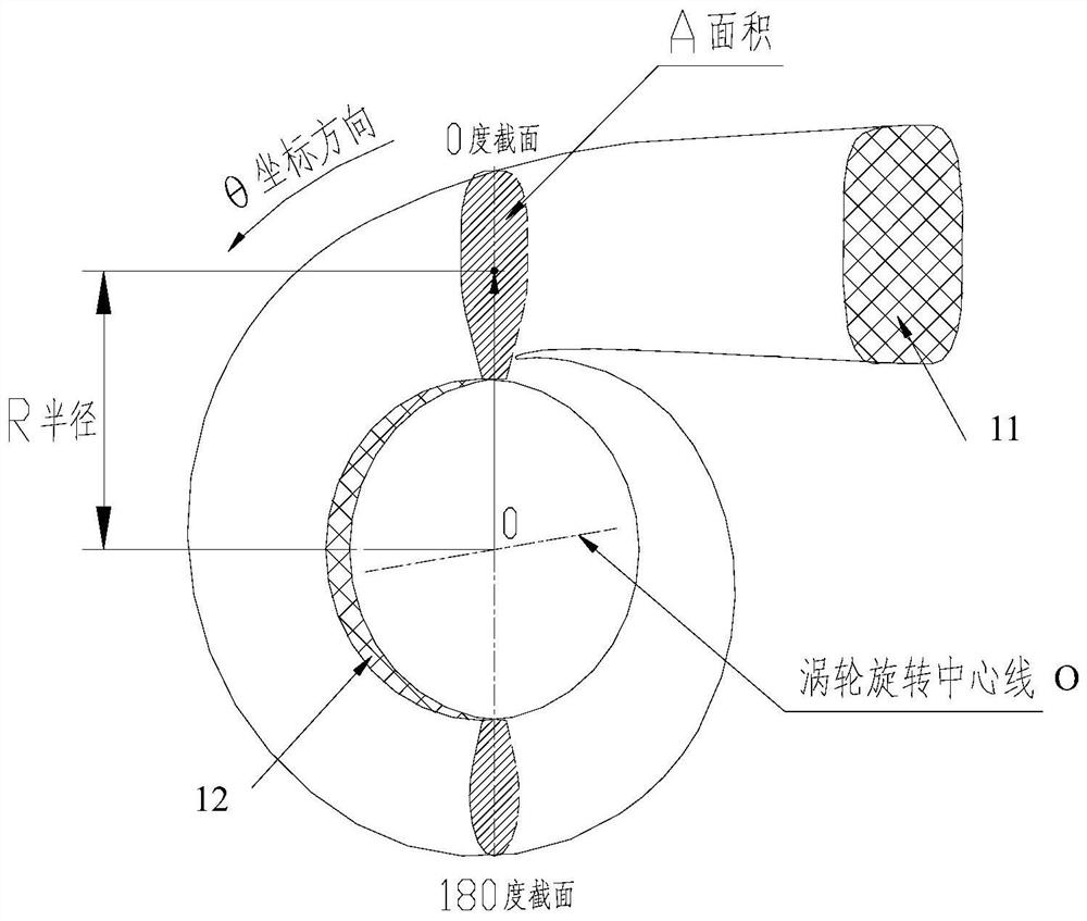
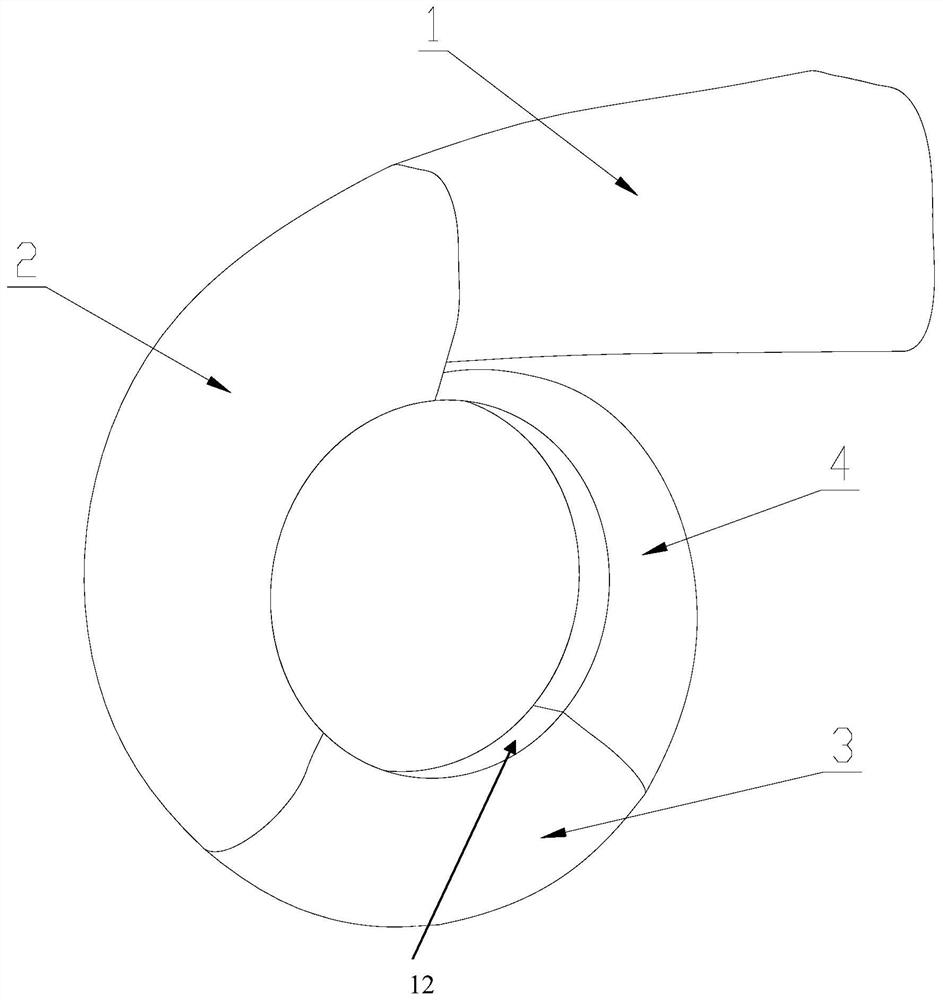
[0082] In embodiment one, the two-stage structure of the turbine box passage is specifically: the passage structure of the large A / R value turning small A / R value (i.e. the first passage section 2 of the large A / R value, turning small A / R channel structure of the second channel segment 4 for the R value).
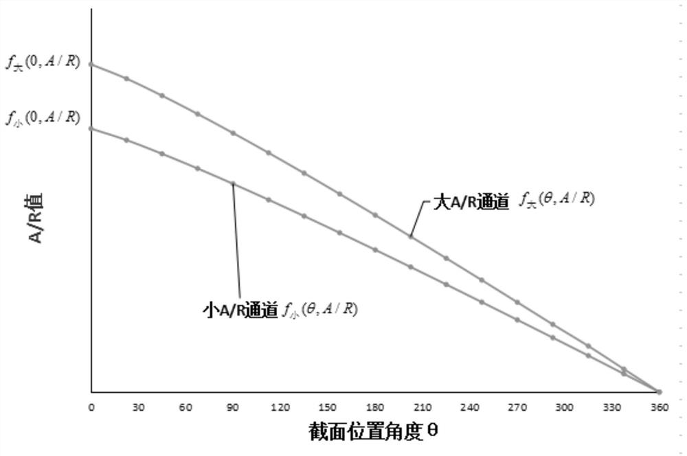
[0083] see image 3 As shown, select the original design of two channels (including the first channel section 2 and the second channel section 4) with different A / R values, where f 大 (0, A / R) and f 小 The A / R value of the (0, A / R) channel (that is, the channel segment with a large A / R value and the channel segment with a small A / R value) is 10-30% different;
[0084] For the present invention, see Figure 4 , Figure 5 As shown, the same first channel section 2 of the turbine selects a large A / R value, that is, f 大 Design parameter f of the first 135 degree channel of (0, A / R) 大 (θ, A / R), the second channel segment 4 selects a small A / R value, namely f 小 (0, A / R) rear...
Embodiment 2
[0089] In embodiment two, the two-stage structure of the turbine box passage is specifically: the passage structure of the small A / R value turning on the big A / R value (i.e. the first passage section 2 of the small A / R value, turning on the big A / R channel structure of the second channel segment 4 for the R value).
[0090] see image 3 As shown, select the original design of two channels (including the first channel section 2 and the second channel section 4) with different A / R values, where f 大 (0, A / R) and f 小 The A / R value of the (0, A / R) channel (that is, the channel segment with a large A / R value and the channel segment with a small A / R value) is 10-30% different;
[0091] For the present invention, see Figure 6 , Figure 7 As shown, the same first channel section 2 of the turbine selects a small A / R value, namely f 小 Design parameter f of the first 135 degree channel of (0, A / R) 小 (θ, A / R), the second channel section 4 selects a large A / R value, namely f 大 (0, A...
PUM
| Property | Measurement | Unit |
|---|---|---|
| Circumferential angle | aaaaa | aaaaa |
Abstract
Description
Claims
Application Information