Optical lens group, camera module and electronic equipment

A technology of optical mirrors and lenses, which is applied in optics, optical components, instruments, etc., can solve the problems of increasing the difficulty of lens design and the limitation of the total length of the lens group, and achieve the effects of miniaturized design, improved resolution, and good imaging quality

Active Publication Date: 2021-05-14
JIANGXI JINGCHAO OPTICAL CO LTD
View PDF5 Cites 0 Cited by
  • Summary
  • Abstract
  • Description
  • Claims
  • Application Information

AI Technical Summary

Problems solved by technology

[0002] With the development and progress of science and technology, portable electronic devices such as smartphones are becoming more and more popular, and people have higher and higher requirements for lenses mounted on electronic products. As portable electronic products are gradually becoming smaller and thinner, the lens group mounted on them The total length is also limited, which increases the difficulty of lens design while ensuring the image quality

Method used


Image

  • Optical lens group, camera module and electronic equipment
  • Optical lens group, camera module and electronic equipment
  • Optical lens group, camera module and electronic equipment

Examples


Embodiment 1

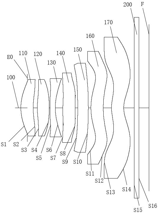
[0079] The structural schematic diagram of the optical lens group in this embodiment refers to figure 1 As shown, the optical lens group includes a first lens 110, a second lens 120, a third lens 130, a fourth lens 140, a fifth lens 150, a sixth lens 160, The seventh lens 170 and the infrared filter 200 , and the diaphragm E0 is disposed between the object plane of the optical lens group and the object side of the first lens 110 .

[0080]Wherein, the first lens 110 has positive refractive power. The object side of the first lens 110 is convex at the near optical axis 100 , and the image side of the first lens 110 is concave at the near optical axis 100 . The object side of the first lens 110 is convex on the circumference, and the image side of the first lens 110 is concave on the circumference.

[0081] The second lens 120 has positive refractive power. The object side of the second lens 120 is convex at the near optical axis 100 , and the image side of the second lens 12...

Embodiment 2

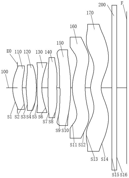
[0107] The structural schematic diagram of the optical lens group in this embodiment refers to image 3 As shown, the optical lens group includes a first lens 110, a second lens 120, a third lens 130, a fourth lens 140, a fifth lens 150, a sixth lens 160, The seventh lens 170 and the infrared filter 200 . And the aperture E0 is disposed between the object plane of the optical lens group and the object side surface of the first lens 110 .

[0108] Wherein, the first lens 110 has positive refractive power. The object side of the first lens 110 is convex at the near optical axis 100 , and the image side of the first lens 110 is concave at the near optical axis 100 . The object side of the first lens 110 is convex on the circumference, and the image side of the first lens 110 is concave on the circumference.

[0109] The second lens 120 has positive refractive power. The object side of the second lens 120 is convex at the near optical axis 100 , and the image side of the secon...

Embodiment 3

[0134] The structural schematic diagram of the optical lens group in this embodiment refers to Figure 5 As shown, the optical lens group includes a first lens 110, a second lens 120, a third lens 130, a fourth lens 140, a fifth lens 150, a sixth lens 160, The seventh lens 170 and the infrared filter 200 . And the aperture E0 is disposed between the object plane of the optical lens group and the object side surface of the first lens 110 .

[0135] Wherein, the first lens 110 has positive refractive power. The object side of the first lens 110 is convex at the near optical axis 100 , and the image side of the first lens 110 is concave at the near optical axis 100 . The object side of the first lens 110 is convex on the circumference, and the image side of the first lens 110 is convex on the circumference.

[0136] The second lens 120 has negative optical power. The object side of the second lens 120 is convex at the near optical axis 100 , and the image side of the second l...


PUM


Abstract

The invention discloses an optical lens group, a camera module and electronic equipment, and the optical lens group comprises a first lens which has positive focal power, wherein the object side surface of the first lens is a convex surface near an optical axis; a second lens which has focal power, wherein the object side surface of the second lens is a convex surface near the optical axis; a third lens which has focal power; a fourth lens which has focal power, wherein the object side surface of the fourth lens is a convex surface near the optical axis, and the image side surface of the fourth lens is a concave surface near the optical axis; a fifth lens which has positive focal power, wherein the object side surface of the fifth lens is a concave surface near the optical axis, and the image side surface of the fifth lens is a convex surface near the optical axis; a sixth lens which has positive focal power, wherein the object side surface of the sixth lens is a convex surface near the optical axis; and a seventh lens which has negative focal power, wherein the image side surface of the seventh lens is a concave surface near the optical axis. By designing the optical lens group composed of seven lenses, the distribution of the lenses in the space can be reasonably distributed to realize the compression of the total length of the lens group, so that the design requirements of ultra-thinness and high resolution are met.

Description

technical field [0001] The present application relates to the technical field of optical imaging, in particular to an optical mirror group, a camera module and electronic equipment. Background technique [0002] With the development and progress of science and technology, portable electronic devices such as smartphones are becoming more and more popular, and people have higher and higher requirements for lenses mounted on electronic products. As portable electronic products are gradually becoming smaller and thinner, the lens group mounted on them The total length is also limited, which increases the difficulty of lens design while ensuring the image quality. The photosensitive element of a general camera lens is a charge-coupled element or a complementary metal oxide semiconductor sensor. With the development of photosensitive element technology, the photosensitive element gradually develops into the field of high pixels, and the pixel size is getting smaller and smaller. T...

Claims


Application Information

Patent Timeline
Patent Type & Authority Applications(China)
IPC IPC(8): G02B13/00G02B13/18
CPCG02B13/0045G02B13/18
Inventor 邹海荣
Owner JIANGXI JINGCHAO OPTICAL CO LTD
Why Eureka
Try Eureka