A device for grabbing and loading discs

A carrier plate and cylinder hole technology, which is applied in the field of grabbing plate devices, can solve the problems of increasing cumulative error and difficult positioning of molds accurately, and achieve the effects of reducing cumulative error, saving time and production materials

Active Publication Date: 2022-08-09
XUZHOU YUNTAI AUTOMOBILE ELECTRICAL APPLIANCE
View PDF0 Cites 0 Cited by
  • Summary
  • Abstract
  • Description
  • Claims
  • Application Information

AI Technical Summary

Problems solved by technology

[0003] In the process of manually placing the insert on the tray, the gripper of the six-axis robot grabs the insert from the tray, and then puts it into the mold, because there is an extra transfer of the gripper of the six-axis robot in the middle, resulting in accumulated errors Increase, when it comes to the precision production of complex inserts, it is difficult to accurately position the mold after multiple transfers, and produce precision-designed products

Method used


Image

  • A device for grabbing and loading discs
  • A device for grabbing and loading discs
  • A device for grabbing and loading discs

Examples


Embodiment 1

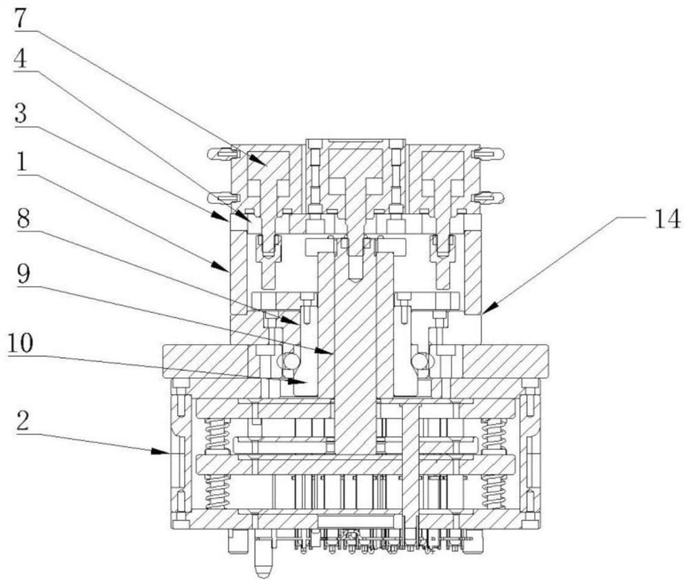
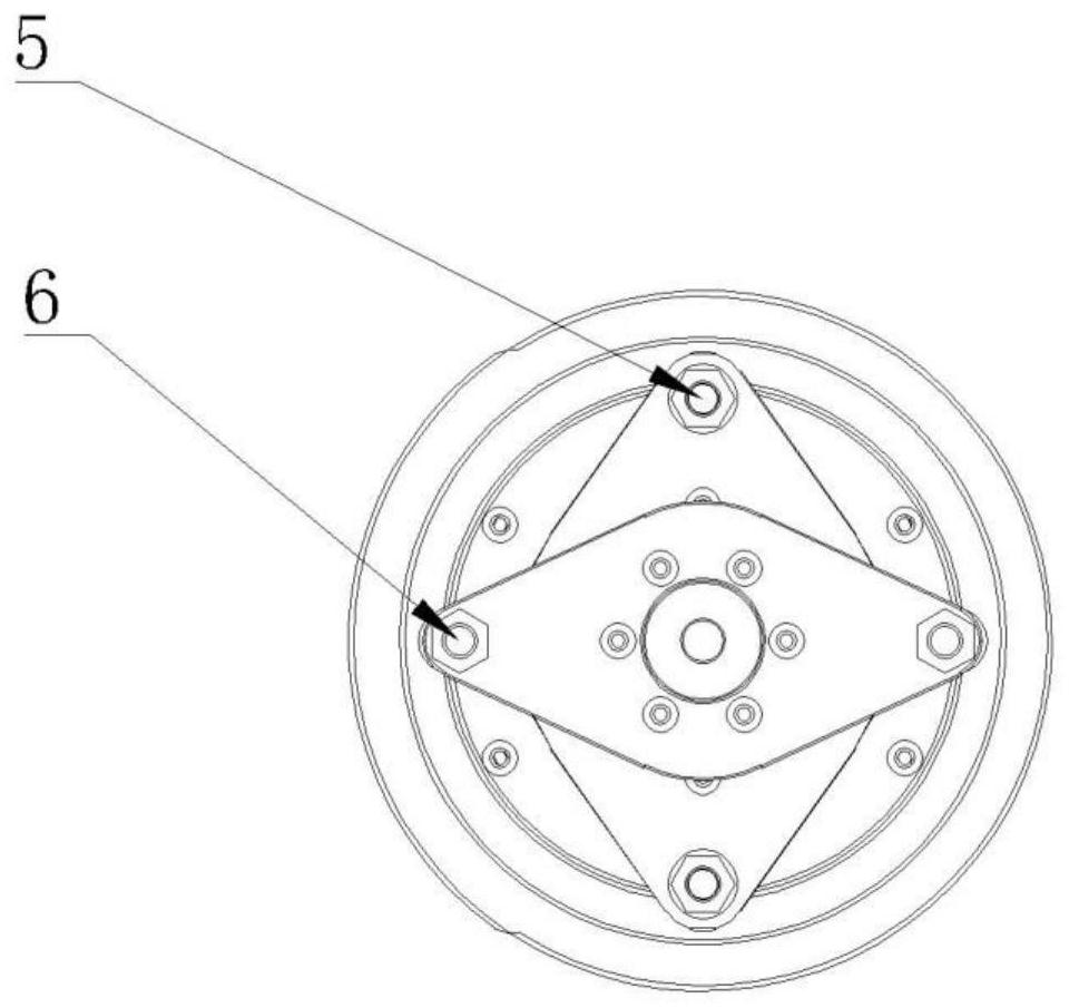
[0033] like Figure 1-3 In this embodiment, there are two cylinder holes 5 in the positioning column, which are arranged in a mirror image according to the center point of the cylinder fixing plate 3; The cylinder 7 is linked with the cylinder 8 through the linkage device 27 . The linkage 27 includes a cylinder piston rod extension 28 and a connecting plate 29 . The cylinder 7 is connected to the cylinder piston rod extension 28 , the cylinder piston rod extension 28 is fixed on the connecting plate 29 , and the connecting plate 29 is fastened on the cylinder 8 . The cylinder piston rod extension rod 28 is fixedly connected with the connecting plate 29 by screws. The connecting plate 29 and the cylinder 8 are fastened with screws and threads. The connecting plate 29 is a diamond-shaped plate, and a through hole for the column body 8 to pass through is provided in the middle of the diamond-shaped plate.

[0034] When in use: let the cylinder 7 push the connecting plate 29, t...

Embodiment 2

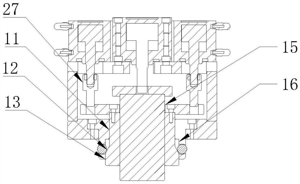
[0037] like Figure 4-5 , This embodiment is based on the first embodiment, the cylinder hole 4 also includes a central column cylinder hole 24 arranged in the center of the plane of the cylinder fixing plate 3, the cylinder linkage central column 25 corresponding to the central column cylinder hole 24, and the central column 25 penetrates through The center of the positioning column 9 is slidably matched with the positioning column 9 ;

[0038] When in use: let the cylinder 7 push the connecting plate 29 and the central column 25, the connecting plate 29 is linked with the column 8, and the column 8, the central column 25 and the carrier body 2 are pressed tightly, and the central column 25 is pressed against the central counterbore 25. Tighten the cylinder of the push column, push the cylinder of the column to pull back the push column 10, push the inclined surface 12 of the column 10 to push the clamping ball 18 into the countersunk hole on the spherical surface, the clampi...

Embodiment 3

[0041] like Image 6 In this embodiment, on the basis of Embodiment 1 or 2, the positioning assembly 19 includes a positioning plate 30 and an assembly plate 31. The positioning plate 30 is placed at the center of the assembly plate 31, and the positioning through hole 21 is placed at the center of the positioning plate 30.

[0042] When in use: let the cylinder 7 push the connecting plate 29 and the central column 25, the connecting plate 29 is linked with the column 8, press the column 8 and the positioning through hole 21 of the positioning plate 30, and the central column 25 and the central counterbore 25 are pressed tightly, Tighten the cylinder of the push column, push the cylinder of the column to pull back the push column 10, push the inclined surface 12 of the column 10 to push the clamping ball 18 into the countersunk hole on the spherical surface, the clamping ball 18 extends out of the countersunk hole 17 on the spherical surface, clamp the spherical groove 22, and ...


PUM


Abstract

The invention discloses a device for grabbing a tray, comprising a clamping jaw body and a tray tray body. The clamping jaw body includes a cylinder fixing plate, the cylinder fixing plate is provided with a cylinder hole, a cylinder is arranged above the cylinder hole, and the cylinder piston rod passes through the cylinder The hole is linked to the stroke operation of the cylinder. The cylinder includes a positioning column and a push column. The push column includes a mating surface, an inclined surface and a push surface; the cylinder fixing plate is connected to a support assembly. The step is provided with a spherical counterbore, and a clamping ball is arranged in the spherical counterbore; the carrier body includes a positioning component and an insert carrier, the positioning component is provided with a positioning through hole in the center of the plane, and the wall of the positioning through hole is provided with a spherical groove. The grooves fit with the snap balls. The invention realizes the precise positioning of the carrier plate through the arrangement of the support assembly and the push column, reduces the transfer of the clamping jaws, and reduces the accumulated error; and realizes automatic production for difficult products with complex inserts.

Description

technical field [0001] The invention belongs to the technical field of molds, and in particular relates to a device for grabbing and carrying disks. Background technique [0002] Insert injection molding is a kind of injection molding model, which is to fix the insert in the appropriate position in the mold in advance, and then inject plastic into the mold. , electrode and other embedded products of the method. In the automated production of precision injection molded parts with inserts, gripper jaws and carrier discs are an important part of the production equipment. Generally, the inserts of the injection molded parts are placed into the insert grooves in the carrier tray manually or by a small four-axis robot for positioning, and then the six-axis robot grabs the inserts on the carrier tray. The corresponding one is to design a set of The six-axis robot gripper is used to grasp the insert corresponding to the carrier plate. After the insert is grasped, the six-axis robo...

Claims


Application Information

Patent Timeline
Patent Type & Authority Patents(China)
IPC IPC(8): B29C45/14
CPCB29C45/14008
Inventor 李含强刘凯
Owner XUZHOU YUNTAI AUTOMOBILE ELECTRICAL APPLIANCE
Why Eureka
Try Eureka