A distribution box with cooling and dehumidification functions

A technology for cooling and dehumidification, distribution box, applied in substation/distribution device casing, visible signal device, cooling/ventilation of substation/switchgear, etc., can solve the problem that electronic components and circuits are easily affected by humid air, The working quality and service life of electronic devices, the inability to effectively reduce the temperature of the distribution box, etc., achieve the effect of strong practicability and market competitiveness, saving long-term use costs, maintenance costs and less difficulty

Active Publication Date: 2021-12-28
SHANDONG UNIV +1
View PDF7 Cites 1 Cited by
  • Summary
  • Abstract
  • Description
  • Claims
  • Application Information

AI Technical Summary

Problems solved by technology

[0002] The distribution box is a commonly used device in power equipment. Generally, there are many electronic components and circuits in the distribution box. During the operation of the distribution box, these electronic components and circuits will continue to emit heat after being powered on. As a result, the temperature in the distribution box rises sharply, and the electronic components and circuits are extremely susceptible to the influence of humid air. High temperature and humidity will seriously affect the working quality and service life of electronic devices.
[0003] In order to solve the above technical problems, those skilled in the art generally set cooling holes or cooling fins on the distribution box, and reduce the temperature in the distribution box through this passive cooling method, and at the same time use a desiccant to maintain the temperature of the distribution box. The dry environment inside; however, the passive heat dissipation method has a limited cooling effect on the distribution box, and cannot effectively reduce the temperature inside the distribution box in high-temperature weather. Increased labor intensity of workers

Method used


Image

  • A distribution box with cooling and dehumidification functions
  • A distribution box with cooling and dehumidification functions
  • A distribution box with cooling and dehumidification functions

Examples


Embodiment Construction

[0039] The present invention is specifically described below in conjunction with accompanying drawing, as Figure 1-14 shown;

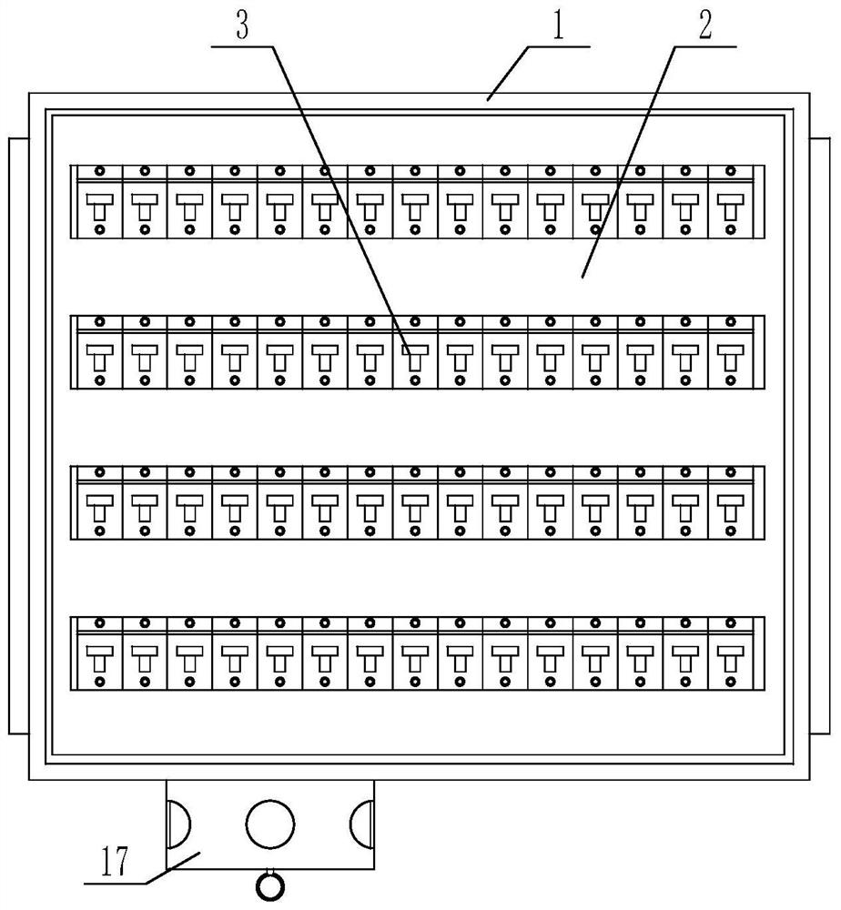
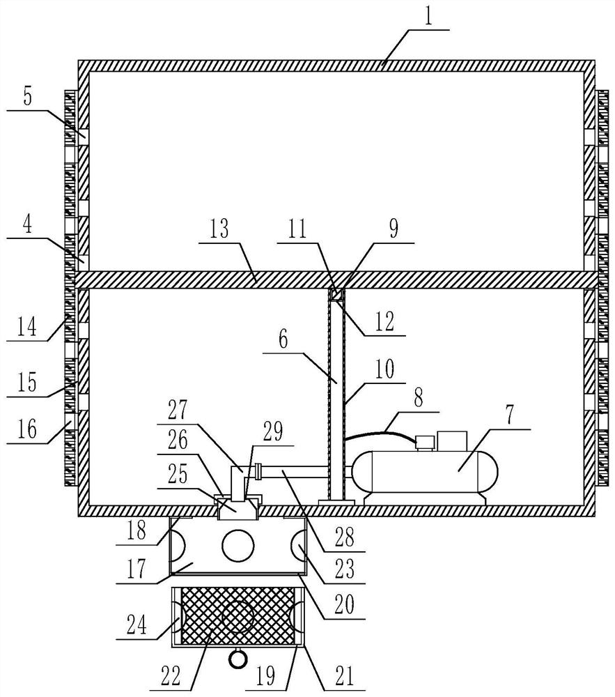
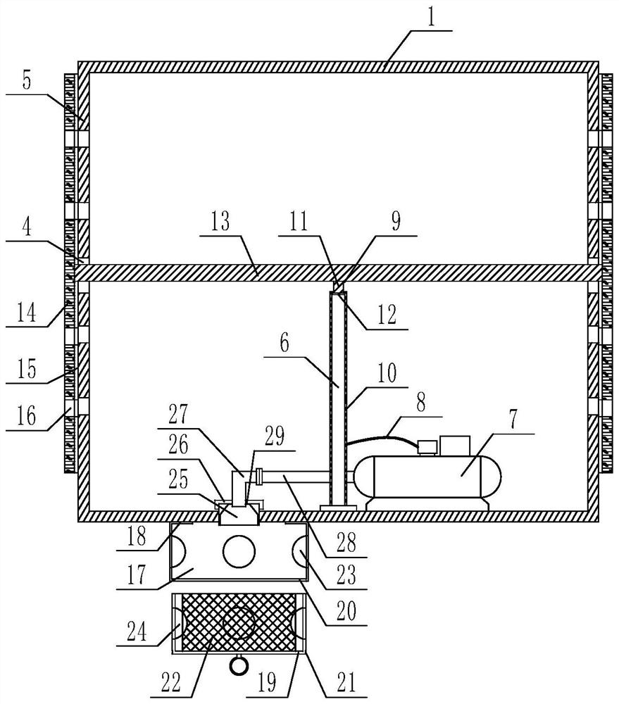
[0040] The invention of the present application lies in that long holes 4 and several ventilation holes 5 are provided on the left and right surfaces of the distribution box, and the long holes and several ventilation holes are located in the rear half of the left and right surfaces of the distribution box. part, the long hole is located in the middle of the rear half of the side surface of the distribution box, the length direction of the long hole is vertically downward along the side surface of the distribution box, and an air duct is arranged inside the distribution box 6 and an electric air pump 7, the lower end of the air guide tube is fixedly connected to the bottom surface of the distribution box, the air guide tube is perpendicular to the bottom surface of the distribution box, the electric air pump is fixedly installed on the bottom surface ...


PUM


Abstract

The invention discloses a distribution box with the function of cooling and dehumidification, which comprises a distribution box. A mounting plate is arranged inside the distribution box. The installation plate divides the inner cavity of the distribution box into front and rear parts. The installation A number of electronic components are fixedly installed on the front surface of the board, and the left and right surfaces of the distribution box are provided with long holes and several ventilation holes, and the long holes and several ventilation holes are located on the left and right surfaces of the distribution box. The second half of the long hole is located in the middle of the second half of the side surface of the distribution box, and the length direction of the long hole is vertically downward along the side surface of the distribution box. There is an air guide tube and an electric air pump, the lower end of the air guide tube is fixedly connected to the bottom surface of the distribution box, the air guide tube is perpendicular to the bottom surface of the distribution box, and the electric air pump is fixedly installed on the bottom surface of the distribution box. The beneficial effect of the invention is that the structure is simple and practical, and has dual functions of heat dissipation and dust removal.

Description

technical field [0001] The invention relates to the technical field of electric equipment, in particular to a power distribution box with the function of cooling and dehumidifying. Background technique [0002] The distribution box is a commonly used device in power equipment. Generally, there are many electronic components and circuits in the distribution box. During the operation of the distribution box, these electronic components and circuits will continue to emit heat after being powered on. As a result, the temperature in the distribution box rises sharply, and the electronic components and circuits are extremely susceptible to the influence of humid air. High temperature and humidity will seriously affect the working quality and service life of electronic devices. [0003] In order to solve the above technical problems, those skilled in the art generally set cooling holes or cooling fins on the distribution box, and reduce the temperature in the distribution box throu...

Claims


Application Information

Patent Timeline
Patent Type & Authority Patents(China)
IPC IPC(8): H02B1/56H02B1/28G08B5/36
CPCH02B1/56H02B1/28G08B5/36
Inventor 刘彧挥燕永振李立广张校玮
Owner SHANDONG UNIV
Why Eureka
Try Eureka