Directional scanning device and method for obtaining real-time position of implant drill

A technology of real-time position and scanning devices, which can be used in dental implants, dental restorations, educational appliances, etc., can solve problems such as unfavorable direct correspondence, measurement result deviation, and human factor interference, and achieve the effect of convenient use and improved accuracy

Active Publication Date: 2022-03-18
SICHUAN UNIV
View PDF8 Cites 0 Cited by
  • Summary
  • Abstract
  • Description
  • Claims
  • Application Information

AI Technical Summary

Problems solved by technology

These three verification methods have the following disadvantages: (1) Visual inspection is prone to misjudgment due to the influence of field of view, observation angle, individual anatomical features, and operator experience; (2) Imaging is performed under the premise of an open wound during surgery Inspection will increase the risk of infection in the operation area, increase the radiation exposure of the patient and the operation time, and the direction indication is poor, which is not conducive to the operator to establish a direct correspondence between the inspection results and the actual operation; (3) The equipment is expensive and the technology is sensitive High, not conducive to program promotion
[0005] In addition, as disclosed in the patent document "Dental Implant Guide Gauge (201410037034.8)", an intraoperative axial checking device is used for comparison. There is not a one-to-one correspondence, and in actual operation, the device is easily blocked by adjacent teeth, vestibular groove, and buccal tissue. There are many human factors in the measurement process, such as the sounding rod is not placed in place, and the needle tip is not fully reached. Bone surface, etc., there will be a large deviation in the measurement result itself, and the individualized jaw shape and thickness will also affect the rationality of the reference value range

Method used


Image

  • Directional scanning device and method for obtaining real-time position of implant drill
  • Directional scanning device and method for obtaining real-time position of implant drill
  • Directional scanning device and method for obtaining real-time position of implant drill

Examples


Embodiment

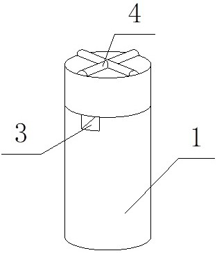
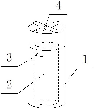
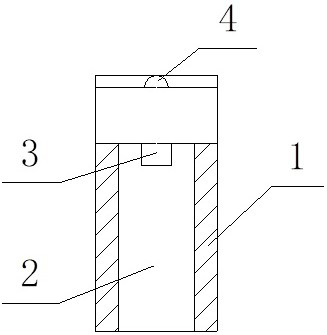
[0036] like figure 1 , figure 2 and image 3 As shown, the orientable scanning device provided in this embodiment for obtaining the real-time position of the implant drill includes a sleeve 1, and a vertical blind hole 2 is opened in the center of the bottom of the sleeve 1, and the blind hole 2 is connected with the sleeve. The barrel 1 is set coaxially, and the diameter of the blind hole 2 matches the drill pin, that is, after the drill pin is inserted into the blind hole 2, the drill pin and the blind hole 2 are in clearance fit, and the top side of the blind hole 2 has a penetrating sleeve 1 the visible window 3 on the side wall, the top of the sleeve 1 is provided with a pointing structure 4 composed of two cross-shaped pointers, the center line of the pointing structure 4 coincides with the axis of the sleeve 1, and the pointing structure One of the pointers of 4 is aligned with visible window 3.

[0037] This embodiment also provides a scanning method using the abov...


PUM


Abstract

The invention discloses an orientable scanning device for obtaining the real-time position of a drill needle in implantation. A visible window runs through the side wall of the sleeve on one side of the top of the blind hole, and the top of the sleeve is provided with a pointing structure composed of two cross-shaped pointers. The present invention cooperates with the oral scanning system to check the position and angle of the drill needle in real time during implantation, and deduces the three-way position of the intraosseous cavity in combination with the direction indicated by the scanning device, and compares and corrects it with the preoperative design, further improving the implantation process. The accuracy of the implant cavity preparation in the center is helpful for the smooth implementation of the subsequent restoration. This method is convenient and simple to operate, and is well matched with the oral scanning system, reducing the operating time of doctors and the time of patients visiting a doctor. This patent is directly nested and connected with the drill, which has wide applicability, and the product is compact and does not occupy too much space in the mouth.

Description

technical field [0001] The invention belongs to the technical field of dental implants, and in particular relates to a device and method for orientable scanning for obtaining real-time positions of implant drills. Background technique [0002] The core process of dental implant surgery is the preparation of the implant cavity and the placement of the implant. Before the dental implant surgery, digital image inspection will be carried out first, and after the CT three-dimensional reconstruction of the upper and lower jaws, the bone quality and bone quality of the patient's operation area will be evaluated, and then combined with the position of the final restoration, the preparation of the implant cavity will be simulated. Determine the ideal placement direction and depth of the implant. During the operation, the operation is completed through several guidance methods such as free hand, static guide plate, and dynamic video navigation. Free hand operation means that the ope...

Claims


Application Information

Patent Timeline
Patent Type & Authority Patents(China)
IPC IPC(8): A61C8/00A61C9/00A61C11/00
CPCA61C8/0089A61C9/0053A61C11/00
Inventor 于海洋吴嘉诚方婷露解晨阳张煜强
Owner SICHUAN UNIV
Why Eureka
Try Eureka