Air inlet cooling and dehumidifying energy-saving device of air compressor

A technology for cooling, dehumidifying, and energy-saving devices, which is applied in mechanical equipment, machines/engines, liquid variable-capacity machines, etc., can solve the problems of increasing the cost of airflow treatment, inconvenient for large-scale promotion, and single structure and function, and achieves improved stability. , Improve the degree of automation, improve the effect of temperature uniformity

Pending Publication Date: 2021-08-31
江苏气老板节能技术有限公司
View PDF6 Cites 1 Cited by
  • Summary
  • Abstract
  • Description
  • Claims
  • Application Information

AI Technical Summary

Problems solved by technology

[0003] In order to solve the problems raised in the above-mentioned background technology, the object of the present invention is to provide an energy-saving device for cooling and dehumidifying the intake air of an air compressor, which has the advantage of saving energy on the basis of air treatment, and solves the problem of existing air intake cooling and dehumidification. The structure and function of energy-saving devices are relatively simple, requiring a large amount of additional energy, which increases the cost of airflow processing, and is not convenient for large-scale promotion

Method used


Image

  • Air inlet cooling and dehumidifying energy-saving device of air compressor
  • Air inlet cooling and dehumidifying energy-saving device of air compressor
  • Air inlet cooling and dehumidifying energy-saving device of air compressor

Examples


Embodiment Construction

[0029] The following will clearly and completely describe the technical solutions in the embodiments of the present invention with reference to the accompanying drawings in the embodiments of the present invention. Obviously, the described embodiments are only some, not all, embodiments of the present invention. Based on the embodiments of the present invention, all other embodiments obtained by persons of ordinary skill in the art without making creative efforts belong to the protection scope of the present invention.

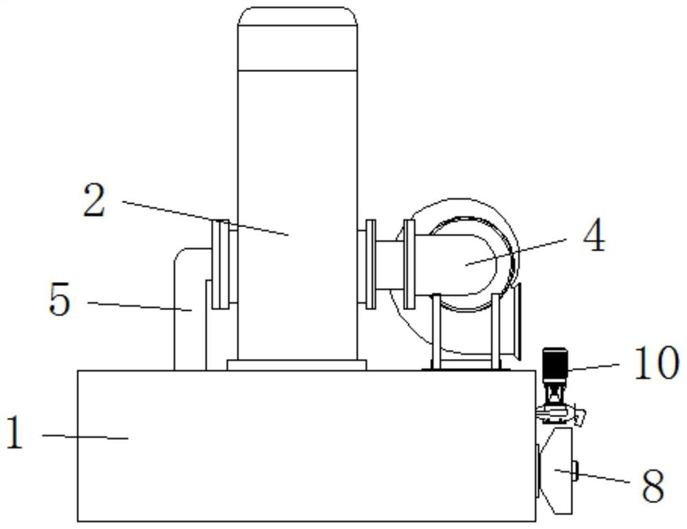
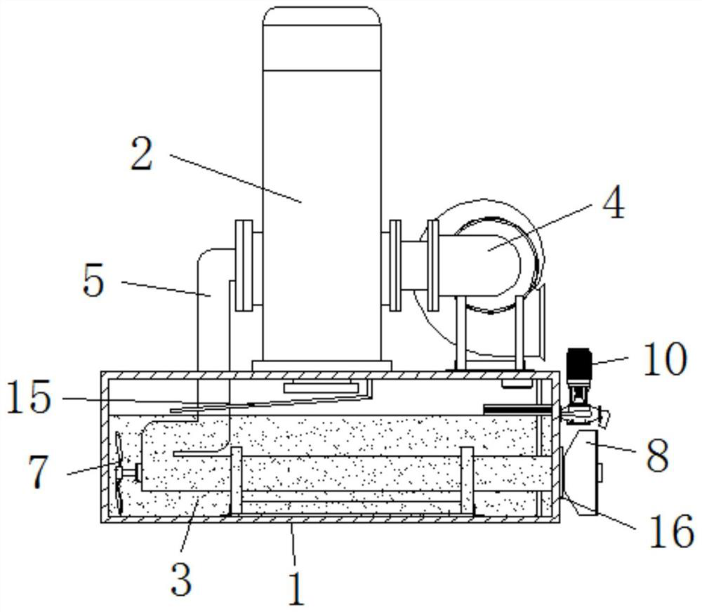
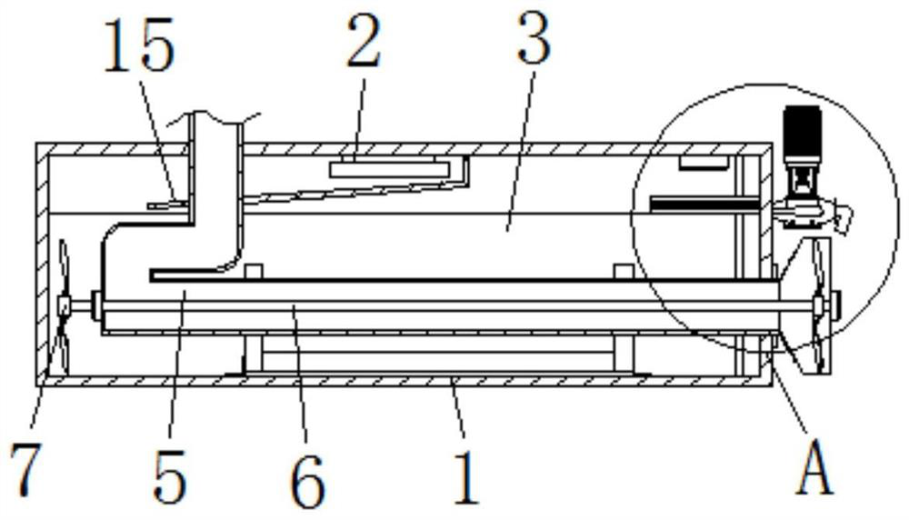
[0030] Such as Figure 1 to Figure 6 As shown, a kind of air compressor intake cooling dehumidification energy-saving device provided by the present invention includes a water tank 1;

[0031] The top of the water tank 1 is fixedly connected with a water vapor separator 2, the drain end of the water vapor separator 2 runs through the water tank 1 and extends to the inside of the water tank 1, the inside of the water tank 1 stores condensed water 3, and the top...


PUM


Abstract

The invention disclose an air inlet cooling and dehumidifying energy-saving device of an air compressor. The air inlet cooling and dehumidifying energy-saving device of the air compressor comprises a water tank, wherein the top of the water tank is fixedly connected with a water-steam separator, the water drainage end of the water-steam separator penetrates through the water tank and extends into the water tank, and condensate water is stored in the water tank. According to the air inlet cooling and dehumidifying energy-saving device of the air compressor, the suction force is released through a fan, and external airflow is guided into the air compressor through a connecting pipe and the water-steam separator; in the airflow circulation process, the airflow and moisture can be separated by the water-steam separator, and the condensate water is discharged into the water tank through the water discharging end of the water-steam separator to be stored; the connecting pipe soaked in the condensate water can reduce the temperature of the airflow, so that the advantage of utilizing the condensate water on the basis of air treatment is achieved, and the problems that an existing air inlet cooling and dehumidifying energy-saving device is single in structure and function, a large amount of energy needs to be additionally used, the airflow treatment cost is increased, and large-scale popularization is not convenient are solved.

Description

technical field [0001] The invention relates to the technical field of air compressor auxiliary devices, in particular to an air compressor air intake cooling, dehumidification and energy saving device. Background technique [0002] In order to improve the operation stability of the air compressor and reduce the impact of humidity and high temperature on the operation of the equipment, the air compressor needs to process the airflow through the air intake cooling dehumidification and energy saving device during use, but the existing air intake cooling The structure and function of the dehumidification energy-saving device are relatively single, which requires a large amount of additional energy, which increases the cost of airflow processing, and is not convenient for large-scale promotion. Contents of the invention [0003] In order to solve the problems raised in the above-mentioned background technology, the object of the present invention is to provide an energy-saving...

Claims


Application Information

Patent Timeline
Patent Type & Authority Applications(China)
IPC IPC(8): F04B39/16F04B39/06
CPCF04B39/16F04B39/06
Inventor 高雄发
Owner 江苏气老板节能技术有限公司
Why Eureka
Try Eureka