Energy-saving fan

A fan and machine body technology, applied in the field of energy-saving fans, can solve the problems of increasing the cleaning frequency of the fan blades, increasing the power consumption of the fan, and increasing the gravity of the fan blades, so as to improve the blowing effect, improve the diversion effect, and improve the fan blade The effect of weight reduction

CN113700661AInactive Publication Date: 2021-11-26罗玉洁
0 Cites 0 Cited by

Patent Information

Authority / Receiving Office
CN · China
Current Assignee / Owner
Publication Date
2021-11-26
Estimated Expiration
Not applicable · inactive patent

Smart Images

  • Figure 1
    Figure 1
  • Figure 2
    Figure 2
  • Figure 3
    Figure 3
Patent Text Reader

Abstract

The invention discloses an energy-saving fan, and relates to the technical field of ventilation equipment. The energy-saving fan comprises a machine body, wherein the interior and the front side of the machine body are hollowed out, an exhaust pipe is arranged at the top of the machine body, a fixing sleeve penetrates through the center of the rear side of the machine body and is fixed to the machine body, and a rotating shaft is sleeved with the fixing sleeve. According to the energy-saving fan, a pneumatic driving plate is arranged, so that the position of an impact cleaning block can be changed by utilizing gas entering the rotating shaft in the rotating process of the rotating shaft; when the fan is closed, the flow of the gas entering the rotating shaft is reduced, the pneumatic driving plate can reset under the action of an elastic piece, and the impact cleaning block can impact the inner wall of the rotating shaft; and vibration generated by impact is transmitted to fan blades so that dust on the fan blades can be separated, and therefore the dust on the surfaces of the fan blades can automatically fall off, the cleaning frequency of the fan blades is effectively reduced, water resources are saved, the weight of the fan blades is reduced after the dust is separated from the fan blades, and the energy consumption of a driving motor is also reduced.
Need to check novelty before this filing date? Find Prior Art

Description

technical field

[0001] The invention relates to the technical field of ventilation equipment, in particular to an energy-saving fan. Background technique

[0002] The fan is a machine that relies on the input mechanical energy to increase the gas pressure and discharge the gas. It is a driven fluid machine. Fan is the customary abbreviation for gas compression and gas conveying machinery. Generally speaking, fans include ventilators, blowers, and wind generators.

[0003] After the existing fan is used for a period of time, the dust in the air will adhere to the surface of the fan blade, causing the gravity of the fan blade to increase, and it needs to be cleaned regularly. Using it in some areas with heavy dust will increase the cleaning frequency of the fan blade, which will cause A lot of water resources are wasted. At the same time, the increase in the weight of the fan blades will also increase the power consumption of the fan and consume additional power. Contents o...

Examples

Embodiment Construction

[0029] The following will clearly and completely describe the technical solutions in the embodiments of the present invention with reference to the accompanying drawings in the embodiments of the present invention. Obviously, the described embodiments are only some, not all, embodiments of the present invention. Based on the embodiments of the present invention, all other embodiments obtained by persons of ordinary skill in the art without making creative efforts belong to the protection scope of the present invention.

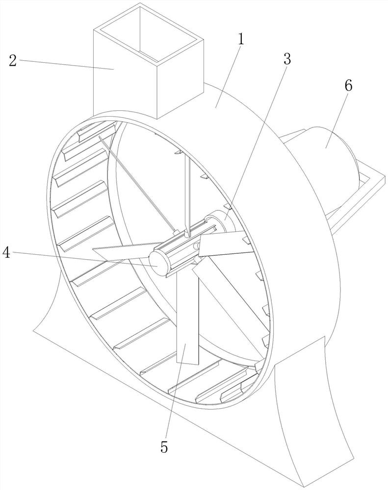
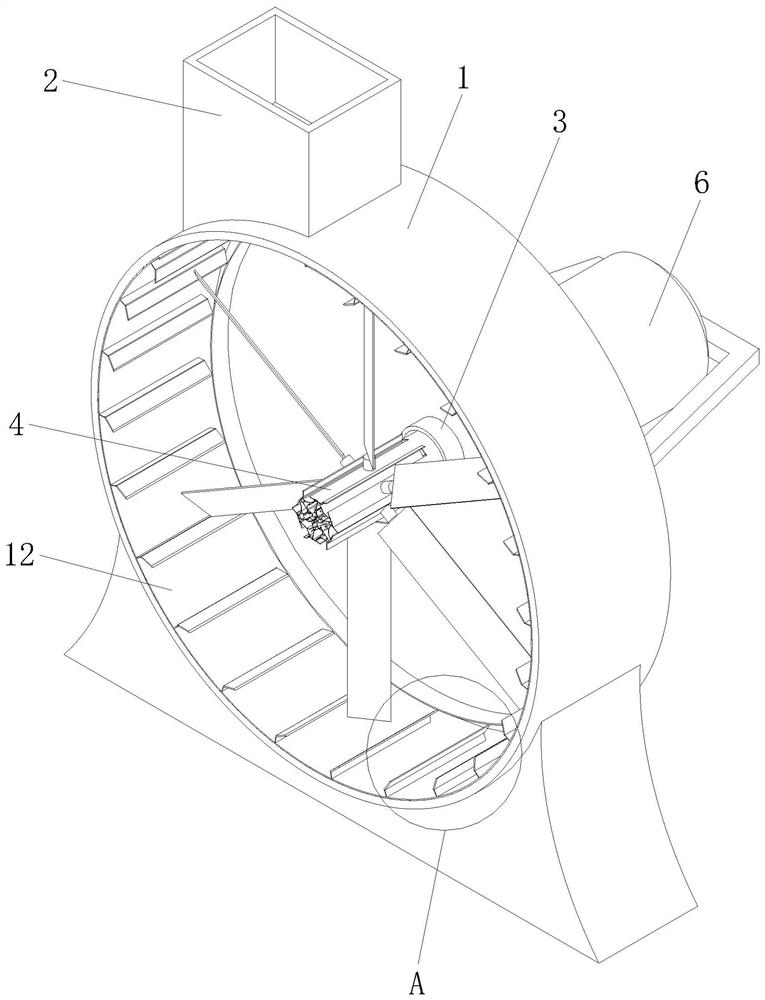
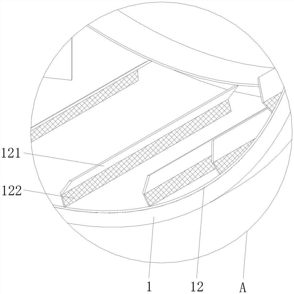
[0030] see Figure 1-6 , the present invention provides a technical solution: an energy-saving fan, including a body 1, the inside and front side of the body 1 are hollowed out, the top is provided with an exhaust pipe 2, and the center of the rear side of the body 1 is penetrated by a fixed sleeve 3 and connected to the The fixed sleeve 3 is fixed, and the inside of the fixed sleeve 3 is sleeved with a rotating shaft 4. One end of the rotating shaft 4 is loca...