Variable steering wheel structure

A steering wheel and variable technology, which is applied to the steering control and handwheels installed on the car, can solve the problems of easy steering of the steering wheel, different operating requirements, and affecting the speed of operating steering, so as to achieve the effect of improving the degree of automation

Active Publication Date: 2021-12-03
HANGZHOU RONG DA INTELLIGENT MFG TECH CO LTD
View PDF14 Cites 0 Cited by
  • Summary
  • Abstract
  • Description
  • Claims
  • Application Information

AI Technical Summary

Problems solved by technology

However, in daily use, it can be found that the diameter of the steering wheel is not all the same. The diameter of the steering wheel will affect the speed and difficulty of steering. The steering wheel is easy to drive, but the operation requirements for different drivers are also different. Some drivers feel that an oversized steering wheel affects the speed of steering, but some drivers feel that a larger steering wheel is easier to turn.

Method used


Image

  • Variable steering wheel structure
  • Variable steering wheel structure
  • Variable steering wheel structure

Examples


Embodiment 1

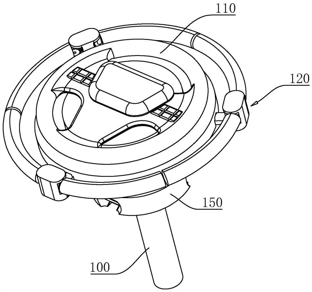
[0043] A variable steering wheel structure, refer to figure 1 , including the linkage frame 100, the end of the linkage frame 100 is equipped with an auxiliary steering wheel 110, the auxiliary steering wheel 110 is provided with the steering wheel body 120, and the steering wheel body 120 is evenly distributed along the circumferential direction. 1, located at 4 o'clock, 8 o'clock, and 12 o'clock respectively. The steering wheel body 120 can be folded and arranged on the sub-steering wheel 110 for changing the overall diameter for easy operation.

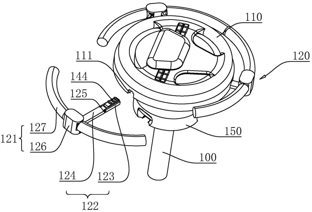
[0044] refer to figure 2, the steering wheel body 120 includes a grip ring 121 and a connecting folding rod 122, the grip ring 121 is connected to the end of the connecting folding rod 122, and the three grip rings 121 will form a complete circle, connecting the folding rod 122 is slidably connected to the underside of the auxiliary steering wheel 110 in the radial direction, and the auxiliary steering wheel 110 is radially prov...

Embodiment 2

[0053] The difference from Example 1 is that, referring to Figure 9 , what is rotationally connected in the auxiliary steering wheel 110 is the linkage ring 160, the side of the linkage ring 160 close to the sliding part 123 has a threaded line 143, and the sliding part 123 has a spiral groove 144 matching with the threaded line 143, the linkage ring 160 There is a rebound block 161 on the outer side, and there is a corresponding sliding groove (not shown in the figure) on the auxiliary steering wheel 110. There is a rebound elastic member in the sliding groove. In this embodiment, the rebound elastic member is a rebound The spring 162 is located in the sliding groove, and one end of the rebound spring 162 is fixedly connected to the rebound block 161 .

[0054] The implementation principle of Embodiment 2 of the present application is: the three connecting folding rods 122 can be stretched out by hand pulling, and the rebound spring 162 will be compressed at this time. The ...

Embodiment 3

[0056] The difference from Example 1 is that, referring to Figure 10 The end of the slideway 111 is rotatably connected with an adjusting gear 170 , and a rotating motor 171 is installed on the slide, and the output shaft of the rotating motor 171 is coaxially connected with the adjusting gear 170 . The rotating part 124 is connected to the fixed part 126 through the hinge shaft 125 , and the hinge shaft 125 has a linkage gear 172 for meshing with the adjusting gear 170 . At the same time, an accommodating groove 173 for the adjustment gear 170 to pass through is defined on the rotating portion 124 along the length direction. That is, when the connecting folding rod 122 moves, the adjusting gear 170 will relatively slide in the receiving groove 173, and when the sliding part 123 moves to the end of the slideway 111, the adjusting gear 170 will mesh with the linkage gear 172 to form meshing, so when the adjusting gear 170 rotates, it will drive the rotating part 124 to rotate...


PUM


Abstract

The invention relates to the technical field of driving control equipment, in particular to a variable steering wheel structure which comprises a linkage frame, an auxiliary steering wheel is arranged on the linkage frame, a plurality of steering wheel bodies are uniformly distributed on the auxiliary steering wheel in the circumferential direction, and the steering wheel bodies are arranged on the auxiliary steering wheel in a foldable mode. Compared with the prior art, the variable steering wheel structure has the advantages that the body is exposed by separating from all the steering wheel bodies, the steering wheel bodies are folded to the lower side of the auxiliary steering wheel at the moment, the small auxiliary steering wheel can be used for operation at the moment, and therefore for drivers with different operation requirements, even two drivers in the same vehicle, adjustment can be easily performed.

Description

technical field [0001] The present application relates to the technical field of driving control equipment, in particular to a variable steering wheel structure. Background technique [0002] The original car was controlled by the rudder. When the engine was changed to be installed on the front of the car, due to the increase in weight, the driver had no way to use the rudder to drive the car. This design of the steering wheel came into being, and the gear system introduced between the driver and the wheels is flexible to operate, and the severe vibration from the road is well isolated. [0003] The steering wheel is generally connected to the steering shaft through splines, and its function is to convert the force exerted by the driver on the edge of the steering wheel into torque and then transmit it to the steering shaft. However, in daily use, it can be found that the diameter of the steering wheel is not all the same. The diameter of the steering wheel will affect the ...

Claims


Application Information

Patent Timeline
Patent Type & Authority Applications(China)
IPC IPC(8): B62D1/04
CPCB62D1/04
Inventor 陈雷王小林王祖光
Owner HANGZHOU RONG DA INTELLIGENT MFG TECH CO LTD
Why Eureka
Try Eureka